background image

Top Cover Assembly Kit Instruction, continued

Sensing and Control
Honeywell
11 West Spring Street
Freeport, IL 61032

62-86-33-25   09/01   Printed in USA 

www.honeywell.com/sensing

Warranty/Remedy

Honeywell warrants goods of its manufacture as being free of defective materials and faulty workmanship.
Contact your local sales office for warranty information. If warranted goods are returned to Honeywell during
the period of coverage, Honeywell will repair or replace without charge those items it finds defective. The
foregoing is Buyer’s sole remedy and is in lieu of all other warranties, expressed or implied, including
those of merchantability and fitness for a particular purpose
. Specifications may change without notice.
The information we supply is believed to be accurate and reliable as of this printing. However, we assume no
responsibility for its use.

While we provide application assistance personally, through our literature and the Honeywell web site, it is up
to the customer to determine the suitability of the product in the application.

Содержание 10260S Series

Страница 1: ...nts which are the local interface for actuator operation The transformer is also mounted inside the top cover The transformer uses the input power to provide internal voltages to the power distribution and main PWA See Figure 1 Follow the procedure in Table 1 to install or replace the top cover assembly Tools Needed To perform the installation procedure you will need the following tools Medium Fla...

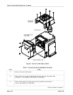
Страница 2: ...able 1 Top Cover Assembly Installation Procedure Step Action 1 Remove AC power to the actuator 2 Remove the seven screws and separate the extended cover from the actuator case See Figure 1 Lay extended cover assembly on a flat surface 3 Remove seven screws and the top cover from the actuator case See Figure 1 Lay top cover assembly on a flat surface Procedure continued on next page ...

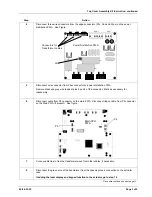
Страница 3: ...n PWA Remove black and gray wire leads at pins 5 and 6 of the connector Mark as necessary for reassembly 6 Disconnect cable from P5 connector on the main PWA Disconnect ribbon cable from P4 connector on the Main PWA if present See figure Main CPU PWA P5 P4 7 Cut any cable ties to free the transformer wires from other cables if necessary 8 Disconnect the green wire of the transformer from the chass...

Страница 4: ...sformer black red and white and alter as necessary For 120 Vac power input Cut red wire and crimp with wire nut For 240 Vac power input Cut black wire and crimp with wire nut Insert the unaltered wire into pin 3 of the Ppwr connector and the white wire into pin 4 of the connector 14 Connect the transformer primary green wire to the chassis ground on the actuator case 15 Insert the black and gray w...

Страница 5: ...overage Honeywell will repair or replace without charge those items it finds defective The foregoing is Buyer s sole remedy and is in lieu of all other warranties expressed or implied including those of merchantability and fitness for a particular purpose Specifications may change without notice The information we supply is believed to be accurate and reliable as of this printing However we assume...

Отзывы: