Mounting and Connection Instructions RF BUS-2 wireless receiver
21
1.
General
1.1
Range of application
The RF BUS-2 wireless receiver is designed for expanding and supplementing compatible hazard detection
systems that provide a BUS-2. By integrating the RF BUS-2 wireless receiver, a bidirectional radio alarm system
featuring the most advanced radio technology can be set up and operated.
This BUS-2 module provides the functions of a gateway that is connected on one side to the hazard detection
central unit by means of a wired connection via the BUS-2. The RF BUS-2 wireless receiver can then communicate
with any 16 stationary mounted radio communication devices via the other side of the bidirectional radio
communication. Depending on the used intruder alarm control panel a appropriate number of RF Panic Buttons
(mobile radio communication device) can be utilized.
In combination with the RF 4I/O wireless module (Item no. 015601.01), conventionally wired detectors and
contacts can be integrated into the radio system. In addition, relay cards (Item no. 015602) that can be inserted
into the RF 4I/O wireless module can be activated by the RF BUS-2 wireless receiver and used for control and
alarm functions. The RF Panic Button can be used for the external and internal arming of the intruder alarm control
panel (IACP). If programmed at the IACP, the RF Panic Button can also be used for additional functions like
transmitting a hold-up alarm as well as e.g. for switching on the outdoor illumination (remote control).
1.2
Connectable radio communication devices
The RF BUS-2 wireless receiver manages the following radio communication devices:
- RF 4I/O wireless module (Item no. 015601 or 015601.01)
- Viewguard PIR RF, wireless motion detector (Item no. 015610 or 015610.01)
- RF Smoke Detector Base (Item no. 015620 or 015620.01)
- RF Panic Button (Item no. 015630)
- RF Magnet contact (Item no. 015640, 015642, 015644), observe the notes in chapter 5.5.5.
1.3
Integration into hazard detection central units
The connection of a hazard detection central unit is done via the BUS-2 connection. The RF BUS-2 wireless
receiver then communicates via the BUS-2 with the corresponding hazard detection system. The wireless
connection of the radio communication devices guarantees a rapid and clean installation. Moreover, the
bidirectional radio link offers at the same time very high connection and communication safety.
All system data and object-specific programming takes place via the “WINFEM Advanced” or “IQ PanelControl”
programming software.
The power supply for the RF BUS-2 wireless receiver is provided by the BUS-2 connection.
1.3.1
Number of attachable radio communication devices
The tables show the maximum number of stationary radio communication devices attachable per RF BUS-2
wireless receiver, the number of the connectable RF Panic Buttons per IACP and the maximum number of all
radio communication devices possible.
RF BUS-2 wireless receiver
16
stationary radio
communication devices
per RF BUS-2 wireless
receiver
- RF 4I/O wireless module
- Viewguard PIR RF
- RF Smoke Detector Base
- RF Magnet contact
MB12 / 561-MB24
561-MB48
561-MB100
MB-Secure
10
RF Panic Buttons
16
RF Panic
Buttons
32
RF Panic
Buttons
32
RF Panic
Buttons
The total number of RF Panic Buttons attachable depends on the used
IACP, not on the number of the used RF BUS-2 wireless receivers.
MB12
561-MB24
561-MB48
561-MB100
MB-Secure
32
64 128
265
512
The total number of stationary radio communication devices attachable depends on the used intruder alarm control panel!
1.3.2
Programming information
Содержание 015600.01
Страница 2: ... ...
Страница 8: ...Montage Anschluss Anleitung RF BUS 2 Koppler 8 3 Fotoübersicht RF BUS 2 Koppler ...
Страница 15: ...Montage Anschluss Anleitung RF BUS 2 Koppler 15 9 Anschlussplan ...
Страница 18: ... ...
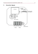
Страница 31: ...Mounting and Connection Instructions RF BUS 2 wireless receiver 31 9 Connection diagram ...


