2
b.
Unplug the Keypad Link connector from the
HWI-TEL9.
c.
Go to every phone in the house and verify that
a dial tone is present on line 1 (and line 2 if
applicable). If a dial tone is not present, a
wiring problem exists.
d.
Unplug the INSIDE PHONE jack on the HWI-
TEL9.
e.
Go to every phone in the house and verify that
a dial tone is
NOT
present on line 1 (and line 2
if wired through the HWI-TEL9).
f.
Any phone that has a dial tone in
step e
is
connected in parallel with the HWI-TEL9 rather
than in series with it, and will not work properly
with the HWI-TEL9. Return to
steps 6 and 7
for instructions on how to properly wire these
phones.
g.
Plug in the Keypad Link connector and the
INSIDE PHONE plug on the HWI-TEL9.
9.
Plug the supplied transformer into the wall and
into the power jack on the HWI-TEL9 unit. There
is a green LED next to the transformer plug which
will light to indicate the 18 V
power.
10.
Return power to the HomeWorks
®
panel.
11.
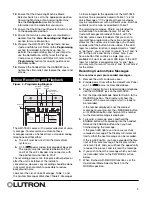
Ensure that the Operational Mode Selector
Switch is set to the Normal position. The Display
will blink “32” (the device’s address) when there
are communications with the
HomeWorks
panel.
It will blink “00” if there are no communications
and will be blank if there is no power being
supplied by the
HomeWorks
Processor.
6.
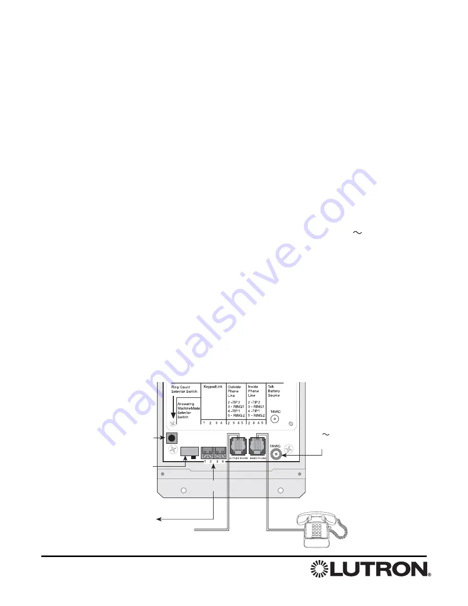
Connect the telephone line from the telephone
company to the jack labeled OUTSIDE PHONE.
The Tip and Ring conductors must be the inner
pair of conductors in the phone plug (see Figure
3).
A standard telephone wiring configuration will
have a second pair of conductors which are
located on the outer pair of a phone plug. The
HWI-TEL9 passes this outer pair directly through
form the OUTSIDE PHONE jack to the INSIDE
PHONE jack so that standard two-line phone
wiring will not require any modifications (Note:
This second pair is not shown in Figure 3).
In the two-line phone configuration, inside access
to the HWI-TEL9 will only be available on line 1
(the inner pair of conductors). Access from line 2
(the outer pair of conductors) will only be possible
by calling line 1 and accessing the HWI-TEL9 in
the same way that it would be accessed from any
outside phone.
7.
Connect the phone wiring for all of the phones
inside the house to the jack labeled INSIDE
PHONE. Again, the inner pair are Tip and Ring for
line 1. The outer pair are for line 2, which is not
used by the HWI-TEL9, but is passed directly
through.
Important Note:
The HWI-TEL9 must be
in a series connection between the telephone
company and any inside phones. The only
devices that should be connected directly to the
telephone company (effectively in parallel with the
HWI-TEL9) are alarm system dialers and other
emergency phone equipment.
8.
When all phone wiring is complete, it should be
tested by performing the following:
a.
Reconnect the telephone lines at the
telephone network interface.
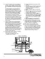
Figure 3 - Panel Wiring
Ring
Count
Selector
Switch
Answering Machine
Selector Switch
(Maximum length: 1000 feet)
KEYPAD
LINK
One pair #18 (1&2)
One pair #18-22 twisted & shielded (3&4)
To HomeWorks Panel
Incoming Line From Phone Co.
to Inside Phones (Inner Pair)
To Inside Phones
(Inner Pair)
18 V
Plug-in
Transformer


