background image

Assembly — Hanging the Fan (continued)

8

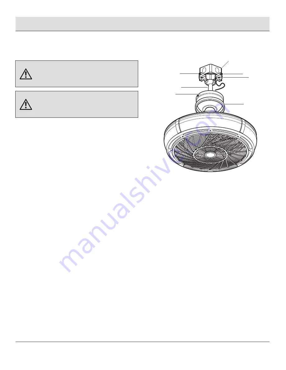
Installing the canopy

WARNING:


The locking slots of the canopy (C) are provided

only as an aid to mounting. Do not leave the fan assembly
unattended until all four canopy mounting screws with lock 
washers (EE) are engaged and firmly tightened.


Slide the canopy (C) up to the ceiling. Make sure you 

have placed the wires safely into the outlet box.

□     

Secure the canopy (C) to the mounting bracket (A) 
with the four canopy mounting screws with lock 
washers (EE) included with your fan.

□     

Raise up canopy ring (B) and line up the four tabs 
with the four grooves on the canopy (C). Once lined 
up, slide the canopy ring (B) and secure it to the 
canopy (C) until snug.

12

WARNING:


Make sure the tab on the mounting bracket (A)

properly sits in the groove in the hanger ball / downrod 
assembly (D) before attaching the canopy (C) to the mounting 
bracket (A) by turning the canopy (C) until it drops into place.

EE

Outlet box

A

EE

D

B

C

Содержание 1005 462 841

Страница 1: ...a m 7 p m EST Monday Friday 9 a m 6 p m EST Saturday 1 800 986 3460 HOMEDEPOT COM HOMEDECORATORS Visual instruction of how to install this fan Visit www homedepot com and enter either the Item or Model number to find this fan and click the link of visual instruction in the product overview section Item 1005 462 868 1005 462 857 1005 462 841 Model AK83 EB AK83 MBK AK83 TM ...

Страница 2: ...ed Package Contents Installation Assembly Hanging the Fan 2 3 4 4 4 4 5 6 7 8 9 Disassembling Your Fan Operation Remote Control Operating Instructions Reverse Switch Operating Instructions Care and Cleaning Troubleshooting Service Parts 13 14 14 15 15 16 17 Table of Contents 2 READ AND SAVE THESE INSTRUCTIONS ...

Страница 3: ...ible for compliance could void the user s authority to operate the equipment NOTE This equipment has been tested and found to comply with the limits for a Class B digital device pursuant to Part 15 of the FCC Rules These limits are designed to provide reasonable protection against harmful interference in a residential installation This equipment generates uses and can radiate radio frequency energ...

Страница 4: ...llation or by affixing any accessories is not covered by this warranty Because of varying climatic conditions this warranty does not cover any changes in brass finish including rusting pitting corroding tarnishing or peeling Brass finishes of this type give the longest useful life when protected from varying weather conditions A certain amount of wobble is normal and should not be considered a def...

Страница 5: ...HOMEDEPOT COM HOMEDECORATORS Please contact 1 800 986 3460 for further assistance DD BB CC AA AA BB CC DD Part Part Description Description 3 6 2 1 Quantity Quantity NOTE Hardware not shown to actual size Plastic wire nut Plastic wire nut 1 5V AAA battery Hex wrench ...

Страница 6: ...d Guard preassembled Decorative frame preassembled Receiver Remote control Quantity Quantity 1 1 1 1 1 Part Part A B C D E F Quantity Quantity 1 1 1 1 1 1 Description Description Mounting bracket preassembled Canopy ring preassembled Canopy Hanger ball downrod assembly Coupling cover Fan motor assembly K J F G H I E A D B C ...

Страница 7: ...uded Installation MOUNTING OPTIONS MOUNTING OPTIONS WARNING To reduce the risk of fire electric shock or personal injury mount the fan to an outlet box marked acceptable for fan support using the screws provided with the outlet box An outlet box commonly used for the support of lighting fixtures may not be acceptable for fan support and may need to be replaced If in doubt consult a qualified elect...

Страница 8: ... up through the downrod MM Thread the downrod MM into the collar Align the holes and replace the clevis pin GG and cotter pin FF Tighten the two collar setscrews HH Slip the coupling cover E canopy ring B and canopy C onto the downrod MM Carefully reinstall the hanger ball JJ onto the downrod MM and reinstall the ground lead LL onto the downrod MM being sure that the cross pin KK is in the correct...

Страница 9: ...ilure to properly seat the tab in the groove could cause damage to the wiring WARNING To reduce the risk of fire electric shock or other personal injury mount the fan only to an outlet box or supporting system marked acceptable for fan support and use the mounting screws provided with the outlet box 9 Pass the 120 volt supply wires through the center hole in the mounting bracket A Attach the mount...

Страница 10: ...he receiver and remote control K CC Setting the Code on the Remote Remove the battery cover on the back of the remote control K by pressing firmly on the arrow and sliding the cover off Slide the code switches to your choice of either up or down The factory setting is up The switch marked O D controls the dimming function of the lights If using non dimmable bulbs use a ballpoint pen or small screw...

Страница 11: ... strands or connections Make wire connections from the fan to the receiver J and outlet box as follows using the wire nuts BB From Fan To Receiver Blue Wire Blue Wire For Light Black Wire Black Wire To Motor L White Wire White Wire To Motor N Make wire connections from the receiver J and fan to the outlet box as follows using the wire nuts AA From Receiver To Outlet Box Black Wire AC in L Black Wi...

Страница 12: ... the outlet box Secure the canopy C to the mounting bracket A with the four canopy mounting screws with lock washers EE included with your fan Raise up canopy ring B and line up the four tabs with the four grooves on the canopy C Once lined up slide the canopy ring B and secure it to the canopy C until snug 12 WARNING Make sure the tab on the mounting bracket A properly sits in the groove in the h...

Страница 13: ...fan for any reason such as cleaning follow these steps below Remove four screw covers NN and remove four hex screws OO from the Decorative frame I by using the hex wrench DD and remove the guard screws OO to disassemble the guard H Remove the blade G from the motor shaft QQ by using the hex wrench DD 13 HOMEDEPOT COM HOMEDECORATORS Please contact 1 800 986 3460 for further assistance F PP QQ H I D...

Страница 14: ...your remote to the D position press and hold the button to activate the dimmer function Press and hold this button for 3 seconds to enable Comfort BreezeTM this will change your fan speed randomly simulating a relaxing breeze To cancel this feature press or While the fan is on press 1 time turns on a 2 hour run timer While the fan is on press 2 times turns on a 4 hour run timer While the fan is on...

Страница 15: ...our fan or motor The motor has permanently lubricated sealed ball bearings Do not Do not 15 HOMEDEPOT COM HOMEDECORATORS Please contact 1 800 986 3460 for further assistance NOTE Wait for the fan to stop before reversing the direction of the blade rotation REVERSE SWITCH OPERATING INSTRUCTIONS REVERSE SWITCH OPERATING INSTRUCTIONS The reverse switch is located on the top of the motor housing Slide...

Страница 16: ... sure the screws that attach the fan blade to the motor hub are tight Make sure the wire nut connections are not rattling against each other or the interior wall of the switch housing Allow a 24 hour breaking in period Most noises associated with a new fan disappear during this time Make sure there is a short distance from the ceiling to the canopy It should not touch the ceiling Make sure your ce...

Страница 17: ... H I J K Description Description Mounting bracket preassembled Canopy ring preassembled Canopy Hanger ball downrod assembly Coupling cover Fan motor assembly Blade preassembled Guard preassembled Decorative frame preassembled Receiver Remote control Part Part AA BB CC DD Description Description Plastic wire nut Plastic wire nut 1 5V AAA battery Hex wrench ...

Страница 18: ...ssing parts Before returning to the store call Home Decorators Collection Customer Service 8 a m 7 p m EST Monday Friday 9 a m 6 p m EST Saturday 1 800 986 3460 HOMEDEPOT COM HOMEDECORATORS Retain this manual for future use ...

Отзывы: