background image

14

DH-Series | Version 1.01

Operation

Fig. 15: Properly earthed socket outlet

Guidelines for extension cords

- Make sure that the extension cord is in good condi-

tion.

- When using an extension cord, be sure to use one 

heavy enough to carry the current your product 
will draw.

- An undersized cord will cause a drop in line 

voltage, resulting in loss of power and cause over-
heating.

- Make sure that the extension cord is properly wired 

and in good condition.

- Always replace a damaged extension cord or 

have it repaired by a qualified person before using 
it.

- Protect your extension cords from sharp objects, 

excessive heat and damp or wet areas.

8

Operation

Erdungszinke

3 Zinken

Stecker

Ordnungsgemäß

geerdete Steckdose

Erdungszinke

3 Zinken

 Stecker

WARNING!
Danger to life!

There is a danger to life for the operator and other 
persons if they do not comply with the following 
rules.
-  The planer may only be operated by an instructed 

and experienced person.

-  The operator must not work when under the influ-

ence of alcohol, drugs or medication. 

-  The operator must not work if he is overtired or suf-

fers from illnesses affecting his concentration.

-  The planer may only be operated by one person. 

Other persons must stay away from the work area 
during operation.

-  Check the machine for damaged parts. If the pro-

tective equipment or guards are damaged, replace 
them immediately.

-  Test whether the moving parts can move freely for 

the necessary function.

ATTENTION!

The following must be observed for safe operation:

-  Do not lean too far forward when operating the pla-

ner. 

-  When operating the planer, always stand securely 

with both legs on the ground and ensure that you 
always keep your balance.

-  Do not work with the machine if the ON/OFF switch 

or the speed controller cannot be moved correctly.

WARNING!

The following must be observed for safe operation:
-  Handle your tools with care: they can be very 

sharp.

-  When the machine is switched on, the workpiece 

must not touch the tools.

-  Let the machine run for a while after turning it on for 

the first cut. During the running-in phase, be aware 
of vibrations or drum noises that indicate improper 
tool attachment.

NOTE!

The use of tools or devices other than those specified in 
the operating instructions may pose a hazard to the 
user.

Содержание DH 330

Страница 1: ...DH 330 Operating Instructions DH S ERIES Planer DH 330 ...

Страница 2: ...Safety 3 2 1 Legend of symbols 3 2 2 Operator responsibility 4 2 3 Operating staff qualification 4 2 4 Personal protective equipment 5 2 5 Safety labels on the planer 5 2 6 For your own safety 6 2 7 General safety instruction 7 2 8 Residual risks 8 3 Intended Use 8 4 Technical Data 9 4 1 Table 9 4 2 Type plate 9 5 Transport packaging storage 9 5 1 Delivery and transport 9 5 2 Packaging 9 5 3 Lager...

Страница 3: ...u make during application of the machine as these may be valuable for product improvements 1 3 Disclaimer All data in this operation manual has been compiled on the basis of the state of the art valid standards and gui delines as well as our many years of expertise and ex perience The manufacturer shall not be liable for damage in the following cases Failure to comply with the operation manual Uni...

Страница 4: ...vide staff with the required pro tective equipment and wearing the required pro tective equipment shall be mandatory Operators shall also be responsible for maintaining the machine in a technically perfect condition For this rea son the following shall apply Operators shall make sure that the maintenance intervals described in these operating instructions are complied with Operators shall regularl...

Страница 5: ...d in the following section 2 5 Safety labels on the planer The following safety labels and instructions are attached to the planer Fig 1 and must be observed t Fig 1 Safety labels 1 Warning of danger 2 Warning of dangerous electrical voltage 3 Warning of danger of entanglement I 4 Ground sym bol l 5 Mandatory signs If safety labels on the machine are damaged or missing this can cause errors person...

Страница 6: ...he operator Work only with the non re turn device functioning correctly Only use sharp pla ning knives Check the workpiece for foreign objects be fore starting work Consider work area s environment Do not use the planer in the rain or in a humid environ ment Ensure that the workplace is adequately lit Do not operate planer near flammable gases or liquids Keep uninvolved persons especially children...

Страница 7: ...eave the machine unattended in operation and remain with the machine until the tool has come to a complete standstill Then pull the mains plug to protect against unintentional switch on Do not remove the workpiece until the tool has come to a complete stop and you have switched off the machine Protect the machine from moisture danger of short circuit Never use electric tools and machines in the vi...

Страница 8: ...issioning operation and maintenance must have the neces sary qualifications to observe these operating in structions exactly In case of improper use may cause danger to persons the planer and other material assets can be endan gered the function of the planer may be impaired Stürmer Maschinen GmbH assumes no liability for con structive and technical changes to the planer Claims of any kind due to ...

Страница 9: ...arpaulin DH 330 Input power drive motor kW 1 5 kW Output power drive motor kW 0 9 kW Electrical connection V 230 V Phase s Ph 1 Mains frequency Hz 50 Hz Max material removal 2 8 2 8 mm Feed speed 6 m min Number of planing knives 2 Sound pressure level Lp 85 dB Sound power level Lw 94 dB Working height max 152 mm Working height min 6 mm Dimension L x W thicknes sing table 235 x 330 mm Max planing w...

Страница 10: ...aner must be installed securely on a level and firm surface Ensure that there is sufficient freedom of move ment for working The place of operation should meet the following criteria The underground must be even solid and vibra tion free The underground must not allow any lubricants to pass through The installation or working area must be dry and well ventilated No machines causing dust or chips s...

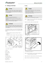
Страница 11: ...ace the washer over the socket head bolt and feed the bolt into the handle Step 4 Tighten the bolt to secure the handle in position Step 5 Place the handle cap onto the handle CAUTION Risk of injury from an improperly installed machine Check the stability of the machine after setting it up on stable ground CAUTION Observe the weight of the machine The machine may only be set up by two persons toge...

Страница 12: ... be fore operation Fig 12 Mounting holes The machine must be anchored in the ground with screws before operation Mounting the suction hose Fig 13 Suction connection Step 1 Mount the suction hose to the adapter ATTENTION Only start up the machine when it is stable NOTE It is recommended that the planer be used with a dust extraction system for a cleaner and safer wor king environment Using a dust e...

Страница 13: ...utlet that is properly installed and grounded in accordance with ALL local regulations DO NOT CHANGE THE CONNECTOR Have the correct socket installed by a qualified electrician if it does not fit into the socket IMPROPER CONNECTION of the equipment grounding conductor can result in risk of electric shock The con ductor with green insulation with or without yellow stri pes is the equipment grounding...

Страница 14: ...ation The operator must not work if he is overtired or suf fers from illnesses affecting his concentration The planer may only be operated by one person Other persons must stay away from the work area during operation Check the machine for damaged parts If the pro tective equipment or guards are damaged replace them immediately Test whether the moving parts can move freely for the necessary functi...

Страница 15: ...planer A spring loaded depth of cut gauge is attached to front of roller case The pointer on depth of cut gauge ac curately displays the depth of cut per pass when work piece is positioned below the gauge Step 1 Cranking the handle moves the roller case down and the pointer shows the desired depth of cut Fig 17 Depth of cut gauge Step 2 Adjust the depth of cut to make an initial light 0 5mm cut No...

Страница 16: ... the top rollers ATTENTION The hands must not get inside the device There is a risk of injury from rotating planing knives Do not tilt the workpiece may strike back Do not remove jammed parts until the motor has stopped and the mains plug has been dis connected Replace blunt planing knives Risk of kickback DANGER Risk of fatal injury due to electric shock Contact with live components may result in...

Страница 17: ...stem does not function or functions only to a limited extent it must be repaired Only then may the planner be put into operation 9 4 Knife replacement If the machine planes unevenly or tends to chisel the knives must be changed Proceed as follows to change the knives Step 1 Remove the dust chute Step 2 Loosen and remove the four screws from the knife cover on the back of the planer Step 3 Remove t...

Страница 18: ... the magnets Step 10 Secure gib to cutterhead using six bolts removed earlier 9 5 Servicing As a result of wear and tear maintenance work may have to be carried out on the machine If the planer does not function properly contact a spe cialist dealer or our customer service The contact de tails can be found in chapter 1 2 Customer service All protective and safety devices must be reinstalled im med...

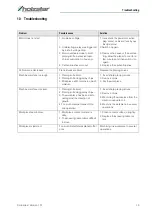
Страница 19: ...achined surface too rough 1 Planing knife blunt 2 Planing knife clogged by chips 3 Workpiece still contains too much moisture 1 Insert sharp planing knives 2 Remove chips 3 Dry the workpiece Machined surface cracked 1 Planing knife blunt 2 Planing knife clogged by chips 3 The workpiece has been machi ned against the direction of growth 4 Too much material planed off in one operation 1 Insert sharp...

Страница 20: ...e corresponding contact data in Chapter 1 2 Customer service Indicate the following basic information for requests or orders of spare parts Type of device Item No Position No Year of construction Quantity Required mode of dispatch mail freight sea air express Address of dispatch Spare part orders which do not include the above indi cations may not be taken into consideration If the indi cations re...

Страница 21: ...drawing The following drawing is intended to identify the required spare parts in the event of service If applicable submit a copy of the parts drawing including the highlighted components to your authorised retailer Fig 24 Spare parts drawing Planer DH 330 ...

Страница 22: ...22 DH Series Version 1 01 Electrical circuit diagram 13 Electrical circuit diagram Fig 25 Electrical circuit diagram ...

Страница 23: ...ith the relevant fundamental health and safety requirements of subsequent EU Directives Relevant EU Directives 2014 30 EU EMC Directive The following harmonized standards have been applied EN 60204 1 2014 10 Safety of machines Basic concepts general principles for design Part 1 General requirements DIN EN ISO 12100 2010 Safety of machinery General principles for design Risk assessment and risk red...

Страница 24: ...www holzstar de ...

Отзывы: