background image

Spare parts

DB-Series | Version 3.09

17

12.4Disposal via municipal collection 

points

Disposal of used electrical and electronic equipment 
(Applicable in the countries of the European Union and 
other European countries with a separate collection sys-
tem for these appliances).

 The symbol on the product or its packaging indi-

cates that this product should not be treated as normal 
household waste, but must be returned to a collection 
point for the recycling of electrical and electronic equip-
ment. By helping to properly dispose of this product, you 
are protecting the environment and the health of others. 
Environment and health are endangered by improper 
disposal. Material recycling helps to reduce the con-
sumption of raw materials. For more information about 
recycling this product, contact your local community, mu-
nicipal waste management, or the shop where you pur-
chased the product.

13 Spare parts

13.1Spare parts orders

Spare parts are available from authorised retailers or di-
rectly from the manufacturer. The contact details have 
been listed in section 1.2 Customer service.

The following key data is required for queries or spare 
parts orders:

- Device type

- Item number

- Position number

- Year of construction

- Quantity

- Desired shipping type (post, freight, sea, air, ex-

press)

- Shipping address

Spare parts orders without the aforementioned data can-
not be taken into account. 

The supplier shall determine the shipping type if no rele-
vant data was provided. Data on the machine type, item 
number and year of manufacture is listed on the type 
plate attached to the device.

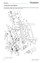
Example

The handwheel for the Wood Lathe DB 900 must be or-
dered. The handwheel has the number 49 in the spare 
parts drawing 1.

By ordering spare parts, send a copy of the spare parts 
drawing (1) with the marked part (handwheel) and mar-
ked positon number (49) to the dealer or spare parts de-
partment and provide the following information:     

- Type of device:   

Wood Lathe DB 900

- Item number:       

5920900

- Drawing number: 

1

- Position number: 

49

DANGER!

Risk of injury caused by the use of 
incorrect spare parts!

The use of incorrect or faulty spare parts may cause 
risks for operating staff and damage as well as mal-
functions.

-  Exclusively genuine spare parts made by the manu-

facturer or spare parts authorised by the manufac-
turer shall be used.

-  Always contact the manufacturer if you are unsure.

NOTE!

The manufacturer warranty shall be rendered void in 
the event of a use of unauthorised spare parts

Содержание DB 1100

Страница 1: ...DB 900 Operating instructions Wood Lathe DB 900 DB 1100 DB 1100 ...

Страница 2: ...ive equipment 5 2 5 Safety labels on the lathe 5 2 6 Safety instructions 6 2 7 Safety instructions for the lathes 6 3 Intended Use 7 3 1 Residual risks 7 4 Technical Data 7 4 1 Type plate 8 5 Transport packaging storage 8 5 1 Delivery 8 5 2 Packaging 8 5 3 Storage 8 6 Description of the device 9 6 1 Machine 9 6 2 Scope of delivery 9 6 3 Accessories not included 9 7 Installation and connection 10 7...

Страница 3: ...are always interested in valuable experience and knowledge gained from using the application whichthen could be shared and be valuable to develop our products even further 1 3 Disclaimer All data in these operating instructions has been com piled on the basis of the state of the art valid standards and guidelines as well as our many years of expertise and experience The manufacturer shall not be l...

Страница 4: ...he personnel with the necessary protective equipment and instruct them to wear the required protective equipment in a bin ding manner Furthermore the operator is responsible for ensuring that the machine is always in perfect technical condition The following therefore applies The operator must ensure that the maintenance inter vals described in these instructions are observed The operator must hav...

Страница 5: ... with the machine which are indicated in the individual paragraphs of these instructions The personal protective equipment is explained in the following paragraph 2 5 Safety labels on the lathe The following safety signs are applied on the lathe Fig 1 which need to be observed and followed Fig 1 Mandatory signs 1 Use eye protection 2 Use ear protection 3 Wear a dust mask Safety markings 4 Warning ...

Страница 6: ...ect the machine from moisture danger of short circuits Never use electric tools and machines in the vicinity of flammable liquids and gases danger of explo sion Before each use of the machine make sure that no parts are damaged Damaged parts must be re placed immediately to avoid sources of danger Do not overload the machine You will work better and safer in the specified power range Use the cor r...

Страница 7: ...terials other than those specified for the intended use Only operate the lathe in a technically perfect condi tion Never machine several workpieces at the same time ATTENTION Certain types of wood and wood products produce harmful dust emissions when processed Therefore only use your machine in a well ventilated room and preferably use an extraction unit ATTENTION The machine may only be operated ...

Страница 8: ...e machine s packaging materials and packing aids are suitable for recycling and must always be dispo sed of using material based recycling systems Packaging materials made of cardboard must be shred ded and disposed of as part of waste paper recycling The foils are made of polyethylene PE padding is made of polystyrene PS Dispose of these substances at a recycling centre or hand them over to the r...

Страница 9: ...tool rest 19 Clamping height adjustment of the tool rest 20 Locking bolt 21 Clamping lever for spindle head 6 2 Scope of delivery Wood Lathe Base frame Face plate diameter 15 cm Travelling tailstock centre Face driver 6 3 Accessories not included Fig 4 Accessories 1 2 3 4 5 7 6 8 9 10 12 14 13 15 11 16 17 19 18 20 21 Description Item No 1 8 part turning tool set 5931011 2 4 jaw chuck set 1 Ø 150 m...

Страница 10: ...s 1 Fig 5 to the bracket Pos 2 Fig 5 using 3 M8x12 round head screws Pos 3 Fig 5 and the corresponding washers Pos 4 Fig 5 and nuts Pos 5 Fig 5 Step 2 Attach the tool rest to the intended position Pos 6 Fig 5 with a total of 8 M8x12 round head screws washers and nuts 8 1 2Assembly of the machine bed Fig 6 Assembly of the machine bed Place the machine frame on a level work surface Lift the machine ...

Страница 11: ...al injury Switched on electrical components can make uncontrolled movements and lead to serious injuries ATTENTION All work on the electrical installation may only be car ried out by a qualified electrician NOTE ON LUBRICATION All moving parts must be lubricated before commis sioning The belt cover must be removed to lubricate the selector and drive shafts Only an adhesive grease may be used here ...

Страница 12: ...on Replacement of the face driver Insert the face drivers manually into the main spindle To loosen it again insert the rod Pos 1 Fig 9 at the back of the main spindle and carefully knock out the face driver Hold it firmly to prevent it from falling down and getting damaged Use the face driver only for work between lace Replacing the travelling tailstock centre Fig 11 Replacing the travelling tails...

Страница 13: ...stock Clamp the spindle to the lever Pos 3 Fig 14 Check by hand whether the workpiece is firmly seated 9 5 Adjusting the tool rest Fig 15 Adjusting the tool rest Use the tool rest for safe guidance of the lathe tool and as a support for the hand A distance of approx 1 3 mm must be set between the workpiece and the tool rest Ad just the tool rest approx 3 mm below the axis of rotation Thinner workp...

Страница 14: ...e poin of the grain must sit firmly in the wood Turn the workpiece by hand to check the tight fit between the tips Technical literature The specialized trade offers literature about turning It is a great help for beginners and experts and also contains many suggestions for processing 10 Care maintenance and repair 10 1Care by cleaning Step 1 Disconnect the mains plug from the socket Step 2 Remove ...

Страница 15: ...e NOTE During the maintenance of the lathe all moving parts must be lubricated at least once a month If required the parts can be lubricated at shorter intervals Lubricating points Fault Possible cause Solution Motor does not start No mains voltage Check mains fuse Switch capacitor are defec tive Have checked by a qualified electrician Electrical extension conduc tor is defective Pull the mains pl...

Страница 16: ...ocal waste disposal authority Consult a specialist disposal agent for recycling if needed 12 3Disposing of lubricants Lubricant manufacturers provide disposal information for the lubricants used If necessary request product spe cific data sheets Strong vibrations Workpiece deformed un round has large weak points cracks or has not been prepa red for turning Prepare the workpiece for turning by plan...

Страница 17: ...ueries or spare parts orders Device type Item number Position number Year of construction Quantity Desired shipping type post freight sea air ex press Shipping address Spare parts orders without the aforementioned data can not be taken into account The supplier shall determine the shipping type if no rele vant data was provided Data on the machine type item number and year of manufacture is listed...

Страница 18: ...are parts drawing DB 900 The following spare parts drawings is intended to help identify the necessary spare parts To order please send a copy of the list of spare parts with the marked components to your dealer Fig 18 Spare parts drawing DB 900 ...

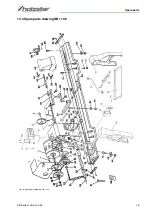
Страница 19: ...Spare parts DB Series Version 3 09 19 13 3 Spare parts drawing DB 1100 Fig 19 Spare parts drawing DB 1100 ...

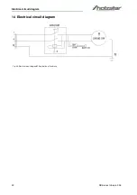
Страница 20: ...20 DB Series Version 3 09 Electrical circuit diagram 14 Electrical circuit diagram Fig 20 Electrical circuit diagramEC Declaration of Conformity ...

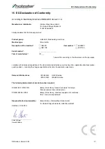
Страница 21: ...nt regulations of the aforementioned directive as well as any other applicable directives subse quently added including the changes applicable at the time the declaration was made Relevant EU directives 2014 30 EU EMC Directive 2012 19 EU WEEE Directive The following harmonized standards have been applied DIN EN ISO 12100 2010 Safety of machinery General principles for design Risk assessment and r...

Страница 22: ...www holzstar de ...

Отзывы: