background image

OPERATION 

HOLZMANN MASCHINEN GmbH   www.holzmann-maschinen.at 

 27


TS 315SE


14


OPERATION 

Device to be operated in a perfect state only. Inspect the device visually every time it is to be 

used. Check in particular the safety equipment, electrical controls, electric cables and screwed 

connection for damage and if tightened properly. Replace any damaged parts before operating the 

device. 

14.1


Operation instructions 


W A R N I N G  


Perform all machine settings with the machine being 

disconnected from the power supply!


N O T I C E  


Operating only with started dust collector! 


Never start the machine when the workpiece is pressed to the saw 

blade! 


Before starting the machine check if the saw blade is tightened


Always adapt cutting speed to the respective working


Use the push stick to avoid the risk of contact with the saw blade


Slide the workpiece evenly, without relapses and without retake it 

until the end of cutting.


14.2


Operation 

Placement of the machine 

For changing the place you have to use the wheels. By lifting the machine at the handles, the machine 

is very easy moved. Regard that the floor is planar. 

Starting/Stopping 

Pushing the green switch 

I

, the machine is turned on. It gets turned off by using the red switch 

0

Adjustment of the blade depth 

Always adjust the blade depth so, that the top of the saw blade 

is about 2-3 cm over the work piece. It is adjusted by the hand 

wheel 

c

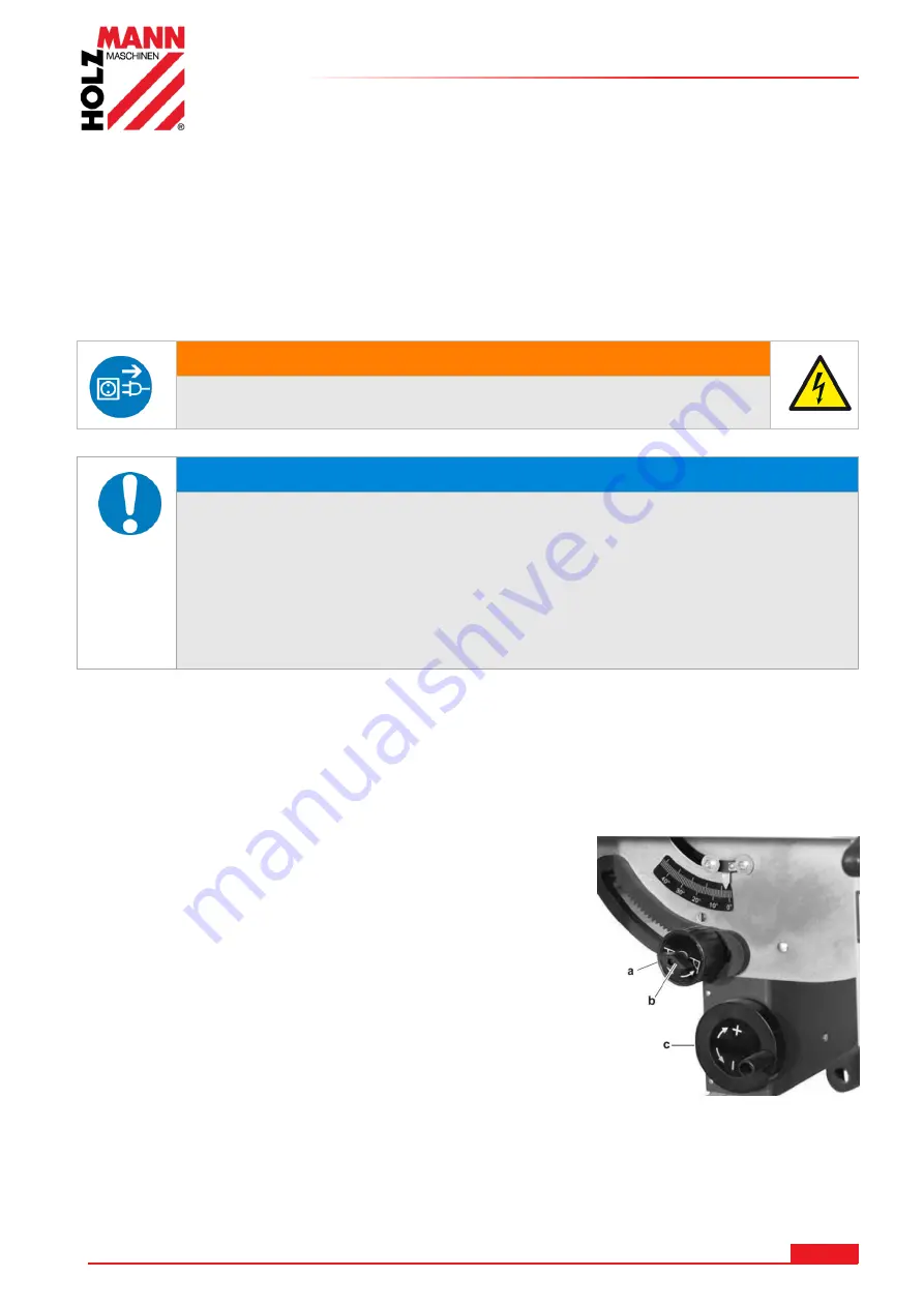
Adjustment of the blade tilt 

For tilted cuts you have to open the lock screw 

b

. Then you have 

to open the second lock screw 

a

. The tilt can now be adjusted 

and read on the scale. Then the two lock screws have to be fixed 

again. 

Adjustment of the fence 

Angular adjustment: At first you have to open the lock screw. The 

angle can be read on the scale. For the most important angles 

there are grooves. Using the detent these angles can be adjusted 

easily. After the adjusting the lock screw must be fixed again. 
Adjustment of the distance to the saw blade: Move the fence to the wished measure which can be 

read on the scale. 


Содержание TS 315SE

Страница 1: ...Edition 29 07 2016 Revision 00 CEC DE EN Originalfassung DE BETRIEBSANLEITUNG TISCHKREISS GE bersetzung Translation EN USER MANUAL TABLE SAW TS 315SE...

Страница 2: ...Restrisiken 11 6 MONTAGE 12 6 1 Standf e 12 6 2 Absauganschluss montieren 12 6 3 Schalter montieren 12 6 4 S geblatt montieren 12 6 5 Spaltkeil montieren 13 6 6 Montage Schiebetisch 13 6 7 Parallelan...

Страница 3: ...5 13 7Rip fence 26 13 8Table extension 26 14 OPERATION 27 14 1Operation instructions 27 14 2Operation 27 15 MAINTENANCE 28 15 1Changing of the saw blade 28 15 2Maintenance plan 28 15 3Cleaning 28 15 4...

Страница 4: ...ker ziehen EN Stop and pull out the power plug before any break and engine maintenance DE CE KONFORM Dieses Produkt entspricht den EG Richtlinien EN CE Conformal This product complies with the EC dire...

Страница 5: ...Bedienung mit offenem Haar verboten EN Operation with long hair forbidden DE Warnung vor Schnittverletzungen EN Warning about cut injuries DE Vor N sse sch tzen EN Protect from moisture DE Achten Sie...

Страница 6: ...inweise Missachtung kann zu ernsten Verletzungen f hren Durch die st ndige Weiterentwicklung unserer Produkte k nnen Abbildungen und Inhalte geringf gig abweichen Sollten Sie Fehler feststellen inform...

Страница 7: ...1 S geblattschutz 8 Schnittwinkeleinstellung 2 S geblatt 36Z 9 Schnitth heneinstellung 3 Parallelanschlag 10 Absauganschluss 4 Schiebetisch mit Winkelanschlag 11 Transportrad 5 Schaltereinheit 12 Arb...

Страница 8: ...ung 230V 50Hz oder 400V 3 50Hz Motorleistung 230V 2 2 kW S6 Motorleistung 400V 2 8 kW S6 Max Schnitth he 90 45 90 50 mm Schwenkbereich S geblatt 0 45 S geblattdimension 315 x 3 x 30 Drehzahl S geblatt...

Страница 9: ...tierte trennende Schutzeinrichtung Die Entfernung bzw nderung der Sicherheitskomponenten k nnen zu Sch den am Ger t und schweren Verletzungen f hren H CHSTE VERLETZUNGSGEFAHR Arbeitsbedingungen Die Ma...

Страница 10: ...weiteren Personen im Gefahrenbereich Mindestabstand 2m aufhalten Wenn Sie an der Maschine arbeiten tragen Sie keinen lockeren Schmuck weite Kleidung Krawatten oder langes offenes Haar Haarnetz verwend...

Страница 11: ...n mit gesundheitssch dlichen Mitteln behandelten Werkst cken Verletzungsgefahr f r das Auge durch herumfliegende Teile auch mit Schutzbrille Verletzungsgefahr durch R ckschlag R ckschlag ist eine pl t...

Страница 12: ...en Sie den Absauganschluss mit drei Schrauben 3 5 x 13 und drei Schrauben M4x8 wie auf der Abbildung dargestellt 6 3 Schalter montieren Montieren Sie den Schalter min den zwei M4 Sicherheitsmuttern un...

Страница 13: ...nen Sie das S geaggregat leicht justieren indem Sie die 6 Fixierschrauben etwas lockern das Aggregat samt S geblatt ausrichten und wieder alle 6 Schrauben festziehen 6 6 Montage Schiebetisch Befestige...

Страница 14: ...anschlag Setzen Sie den Parallelanschlag auf die Schiene L sen sie mit dem Spannhebel den Parallelanschlag und schieb ihn in die gew nschte Position Danach mit Spannhebel wieder fixieren 6 8 Tischerwe...

Страница 15: ...Durch die Griffe ist die Maschine so relativ einfach zu transportieren Achten Sie bei der Wahl des Arbeitsplatzes darauf dass der Boden eben ist Starten Stoppen Durch Dr cken des gr nen Schalters I w...

Страница 16: ...umgekehrten Reihenfolge vor 8 2 Instandhaltung und Wartungsplan Kontrollen zur Instandhaltung der Maschine Lockere oder verlorene Schrauben Vor jeder Inbetriebnahme Besch digung irgendwelchen Teiles V...

Страница 17: ...eiss geblatt Verwenden Sie ein f r Ihr Material empfohlenes Kreiss geblatt Sch rfen bzw ersetzen Schnittgeschwindigkeit an Werkst ckh rte Motorleistung anpassen Material R ckschlag Stumpfes Kreiss geb...

Страница 18: ...advancements in product design construction pictures and content may diverse slightly However if you discover any errors inform us please Technical specifications are subject to changes Please check...

Страница 19: ...1 Blade protection cover 8 Cutting tilt adjustment 2 Blade 36T 9 Cutting height adjustment 3 Rip fence 10 Dust collector plug 4 Sliding table with mitre gauge 11 Transport wheel 5 Switch unit 12 Tabl...

Страница 20: ...315SE Voltage 230V 50Hz or 400V 3 50Hz Motor power 230V 2 2 kW S6 Motor power 400V 2 8 kW S6 Max cutting height 90 45 90 50 mm Blade tilt range 0 45 Blade dimension 315 x 3 x 30 Blade speed 2800 min...

Страница 21: ...y saw blades allowable for this machine EN 847 1 Never use damaged saw blades Never use the machine with defective or without mounted guard The removal or modification of the safety components may res...

Страница 22: ...ent in the dangerous area The minimum safety distance is 2m Wear suitable work clothes Do not wear loose clothing or jewelry as they might be caught and cause severe accidents Wear a hair net if you h...

Страница 23: ...be observed with regard to clothing Risk of injury due to contacting with live electrical components Risk of injury due to dust emissions treated with harmful agents workpieces Risk of injury to the...

Страница 24: ...fasten through wing nut 13 2 Dust collector plug Attach the suction port with three taping screws ST 3 5x13 and two pan head screw M4X8 as illustrated to the outside of the chip case 13 3 Switch Fit...

Страница 25: ...45 bevel position Loosen the six hexagonal self locking nuts holding the fastening brackets under the saw table by approx one turn Move the fastening brackets with the motor unit chipcase assembly att...

Страница 26: ...as rip fence the long fence extrusion must be installed It is mounted on the guide extrusion at the front of the table Slide the head of the carriage bolts into the guide extrusion 13 8 Table extensio...

Страница 27: ...cutting 14 2 Operation Placement of the machine For changing the place you have to use the wheels By lifting the machine at the handles the machine is very easy moved Regard that the floor is planar S...

Страница 28: ...Now loose the flange Change the saw blades For the assembly you have to do these steps backwards 15 2 Maintenance plan Loose or lost screws nuts bolts Regularly prior to each operation Damage of any p...

Страница 29: ...ood Always cut with convex side to table surface Wood edges away from rip fence when ripping Saw does not make accurate 90 or 45 cuts Ripping fence is misaligned Positive stops inside cabinet need adj...

Страница 30: ...SCHALTPLAN WIRING DIAGRAM HOLZMANN MASCHINEN GmbH www holzmann maschinen at 30 TS 315SE 17 SCHALTPLAN WIRING DIAGRAM 230V 50Hz 400V 3 P 50Hz...

Страница 31: ...hnung an Um Missverst ndnissen vorzubeugen empfehlen wir mit der Ersatzteilbestellung eine Kopie der Ersatzteilzeichnung beizulegen auf der die ben tigten Ersatzteile eindeutig markiert sind Bestellad...

Страница 32: ...ERSATZTEILE SPARE PARTS HOLZMANN MASCHINEN GmbH www holzmann maschinen at 32 TS 315SE 18 2 Explosionszeichnung explosion drawing...

Страница 33: ...ERSATZTEILE SPARE PARTS HOLZMANN MASCHINEN GmbH www holzmann maschinen at 33 TS 315SE...

Страница 34: ...m 76 Riving knife seat 24 Locking washer 77 Carriage bolt M 10X25 25 Locking washer 78 Guide plate 26 Washer 5mm 79 Lever 27 Pinion shaft support 80 Riving knife 28 Pan head screw M5X12 81 U plate 29...

Страница 35: ...EN 61000 3 3 Hiermit erkl ren wir dass die oben genannten Maschinen aufgrund ihrer Bauart in der von uns in Verkehr gebrachten Version den grundlegenden Sicherheits und Gesundheitsanforderungen der an...

Страница 36: ...e nicht abgedeckt E Garantieausschluss bei M ngeln an Maschinenteilen welche gebrauchsbedingten oder sonstigen nat rlichen Verschlei unterliegen sowie M ngeln an der Maschine die auf einen gebrauchsbe...

Страница 37: ...ace of fulfillment is principally the HOLZMANN Service Center in Haslach Austria Transport charges for sending to and from our Service Center are not covered in this guarantee E The Guarantee does not...

Страница 38: ...ts in the frame of a Quality Management policy Um einen st ndigen Verbesserungsprozess gew hrleisten zu k nnen sind wir von Ihnen und Ihren Eindr cken beim Umgang mit unseren Produkten abh ngig Your o...

Страница 39: ......

Отзывы: