background image


BA_PH_245-20_EN_15-22.docx


8


2.2


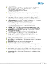
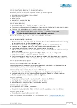
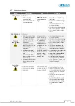
Symbols in Safety Instructions


Symbol 

Safety Instruction 


General danger symbol, which requires the highest attention!  

Failure to observe may result in damage to the equipment, serious injury or even death. 


Warning of possible danger from forklift traffic! 

Non-observance may result in life-threatening injuries. 


Warning indicates a possible hazard under suspended loads! 

Non-observance may result in life-threatening injuries. 


Warning indicates a possible fall hazard! 

Non-observance of these instructions may result in serious injuries. 


Warning indicates a possible cutting hazard! 

Risk of personal injury and possibly additional damage to equipment.


Reference to the obligation to wear protective gloves! 

Non-observance of these instructions may result in personal injury. 


Reference to the obligation to wear hearing protection! 

Non-observance of these instructions may result in personal injury. 


Reference to the obligation to wear protective goggles! 

Non-observance of these instructions may result in personal injury. 


Reference to the obligation to wear a respiratory protection mask! 

Non-observance of these instructions may cause breathing difficulties and lung damage.


Reference to the obligation to wear safety shoes! 

Non-observance of these instructions may result in personal injury.


Possible dangerous crushing hazard in the area of stationary objects! 

Risk of personal injury and possibly additional equipment damage. 


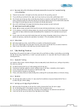
Reference to a possible crushing hazard!  

Non-observance increases the risk of injury to hands and fingers! 


This symbol warns of the dangers of electric voltage!  

Failure to observe may result in damage to the equipment, serious injury or even death. 


Fire hazard! Do not smoke and do not ignite open fire.


Access for unauthorized persons prohibited! 

Risk of personal injury and possibly additional equipment damage.


This safety notice indicates a possible dangerous pull-in hazard! 

Wearing loose clothing, jewellery as well as long untied hair is prohibited! 

Risk of personal injury and possibly additional damage to property. 


Содержание PANHANS 245-20

Страница 1: ...au GmbH Graf Stauffenberg Kaserne Binger Str 28 Halle 120 DE 72488 Sigmaringen Tel 49 07571 755 0 E Mail info hokubema panhans de Web https hokubema panhans de Operating Manual Tilting Spindle Moulder Table Milling Machine PANHANS 245 20 Machine Type 245 20 ...

Страница 2: ... Protection Regulations 15 4 2 5 Organisational Measures 15 4 2 6 Personnel Selection and Qualification Basic Duties 16 4 3 Safety Instructions for Specific Phases of Operation 16 4 3 1 Before Working 16 4 3 2 Normal Operation 17 4 3 3 Special work within the Scope of Maintenance Work as well as Troubleshooting in the Workflow 18 4 3 4 After Work 18 4 4 Safe Working Practices 18 4 4 1 Operator Tra...

Страница 3: ...ctrical Connection 29 8 1 Back up Fuses on site 29 8 2 Machine Socket 29 9 Components and Control Elements 30 9 1 Machine 30 9 2 Control Panel 31 10 Commissioning 32 10 1 Switching ON and OFF 32 10 1 1 Selecting the Rotational Direction 32 10 1 2 Switch on the Milling Spindle 32 10 1 3 Switch off the Milling Spindle 32 10 2 Emergency Stop Function 33 11 Speed Setting 33 11 1 Cutting Speed Chart 33...

Страница 4: ...ge 47 14 4 2 Ring Fence TAPOA 1639 48 15 Protection and Pressure Devices 49 15 1 TYPE 1629 GAMMA V Standard 49 15 2 TYPE 1624 CENTREX Option 49 16 Optional Components 50 16 1 Integral Fence System 50 16 1 1 Operation and Functions 50 16 2 Table Slide Plate 50 16 3 Safety Rulers for the Milling Fence 51 16 4 Swivel away Device for the Milling Fence 51 16 5 Turntable 360 degrees for the Milling Fenc...

Страница 5: ... 5 Roller Table Cross Cut Fence and Tenoning Device 66 20 6 Power Feeders and Consoles 67 20 7 Special Accessories 67 21 Disassembly and Scrapping 68 EU Declaration of Conformity 69 List of Figures Figure 1 Milling arbor with cutter head 7 Figure 2 Nameplate 23 Figure 3 Working area 24 Figure 4 Dimensions front view 25 Figure 5 Dimensions top view 25 Figure 6 Transport pallet 26 Figure 7 Lashing p...

Страница 6: ...ure device 1629 GAMMA V 49 Figure 42 Protection and pressure device 1624 CENTREX 49 Figure 43 Integral fence system option 50 Figure 44 Integral fence system operation and functions 50 Figure 45 Optional Table Slide 50 Figure 46 Safety ruler set 51 Figure 47 Turntable with opening for clamping 51 Figure 48 Clamping lever for extendable frame support 52 Figure 49 TM 100 Machine Access Control Syste...

Страница 7: ...emoval of pro duction waste and maintenance during maintenance servicing inspection repair and or during transport Apart from the operating manual and the legally binding accident prevention provisions applicable in the country and place of use the recognized technical regulations for safe and proper work must also be observed 1 1 Legal Notice All contents of these operating instructions are subje...

Страница 8: ... to the obligation to wear protective goggles Non observance of these instructions may result in personal injury Reference to the obligation to wear a respiratory protection mask Non observance of these instructions may cause breathing difficulties and lung damage Reference to the obligation to wear safety shoes Non observance of these instructions may result in personal injury Possible dangerous ...

Страница 9: ... with digital LCD position indicator The partial fence is adjusted via a star grip via vernier scale With the optional fence type 204 both the total and partial fence are adjusted via a digital handwheel The finely planed cast iron machine table has the dimensions 1100 x 760 mm and is provided with a rigid frame support Extendable frame supports as well as a turntable are optionally available Also...

Страница 10: ...e g apprenticeship as carpenter machine fitter etc and or practice in operat ing tilting spindle moulders resp woodworking machines Reading and understanding these operating and maintenance instructions In order to acquire the knowledge required to operate this machine the operator must ensure the following measures Product training for every operator also possible external personnel Regular safet...

Страница 11: ...or bypass any protective safety or monitoring equipment It is forbidden to modify or alter the machine without the written approval of the manufacturer supplier Faults or damage must be reported to the operator immediately eliminated without delay and repaired if necessary For repairs only original spare parts may be used All protective safety and monitoring devices must be regularly checked and m...

Страница 12: ...gital handwheels for position adjustment Milling spindles Ø 35 mm 40 mm 50 mm 1 not retrofittable Machine access control via RFID key system with personalised keys Single and double sided table top extensions with frame support Power feeder types PV84 and VARIOMATIC 4 N and consoles Milling protection and pressure device type 1624 CENTREX Hydraulic swivel away device for milling fence Milling arbo...

Страница 13: ...r to persons and to a defect or damage to the machine Only workpieces that can be safely placed and guided may be machined Metallic materials must not be machined The machine is not suitable for operation outdoors or in potentially explosive areas Permissible ambient temperature 5 40 C Permissible humidity 30 90 Number of workplaces 1 The speed limits indicated on the tool must be strictly adhered...

Страница 14: ...ersons are not allowed to enter the installation area of the machine responsibility of the operator Be aware of possible tripping and slipping hazards on the floor Prevent possible hazards by keep ing the floor dry and clean and by using anti slip floor coverings around the machine Be aware of the danger from falling objects such as workpieces tools or similar Therefore wear safety shoes especiall...

Страница 15: ...Avoid leakage of hazardous substances by using suitable collection contain ers Ensure that the above mentioned substances are disposed of by a qualified dis posal company 4 2 5 Organisational Measures Always keep this operating manual within easy reach and at the place of use of the machine In addition to the operating manual observe and instruct on generally applicable legal and other binding reg...

Страница 16: ...ne are to be reported immediately after detection Any mode of operation that compromises safety is prohibited Sufficient lighting around the machine must be ensured at least 500 Lux 4 3 1 Before Working Clean the machine table from dirt and chips and provide containers for waste pieces Only use tools in perfect sharpened condition and with clean clamping surfaces Always check workpieces to be mach...

Страница 17: ...t an angle of approx 5 to the feed direction and keep the opening to the fence as small as possible Manual feeding When feeding the workpiece manually place the hands flat on the workpiece with closed fingers and push forward evenly Special tools For certain operating phases and operations it is necessary to use special tools e g feed device table extensions clamping drawer push bar or comparable ...

Страница 18: ... Secure the machine against unauthorised use and never leave it unattended in an unsecured condition Clean the machine with an industrial hoover avoid compressed air 4 4 Safe Working Practices Depending on the work to be carried out the guards must be used for fence milling insert milling curved milling and also for tenoning Nevertheless in order to prevent accidents it is necessary that the user ...

Страница 19: ... rotation Climb milling with manual feed involves considerable dangers This operation is only permitted with ap propriate devices and suitable tools If the machine is switched to climb milling this dangerous operation is signalled by a signal lamp on the control panel 4 4 8 Speed Selection The user must ensure that the correct speed is selected for the clamped tool For the optimum cutting speed pl...

Страница 20: ...curely fastened front cross fence as well as a kickback guard e g type 1648 see section 16 10 must also be used For very long workpieces use an auxiliary fence if necessary Quick clamps acting either via toggle levers or eccentrics ensure fast and convenient workpiece clamping Quick clamps acting either via toggle levers or eccentrics ensure fast and convenient workpiece clamping Rear and or front...

Страница 21: ...it as small as possible The service door at the front is equipped with a safety switch This prevents the milling spindle spindle motor from being switched on when the door is open The TAPOA 1639 ring fence guard is used for accident free milling of curved workpieces using a template For tools up to Ø 160 mm with thrust and protection ring suction nozzle and transparent protective cover 4 4 13 Opti...

Страница 22: ... even death from ejected or fly ing workpieces workpiece parts and tool parts e g in the event of tool breakage Increased risk of in juries or even death due to entrapment of hands fingers clothing jewellery and long hair Use all available tool covers and fence bridges Do not push workpieces along the unsecured cutter by hand Use a power feeder or sliding block Use an anti kickback device also for...

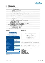
Страница 23: ...ionally 45 5 45 5 Height Tilt Adjustment via positioning control unit Digital Indicators height angle speed Suction Nozzles 2 pieces Ø 120 mm Net Weight approx 800 kg Space Requirement 1200 x 1400 mm Nameplate Figure 2 Nameplate Manufacturer Expandability The machine is prepared for the later addition of special ac cessories see chapter 20 from the extensive manufac turer portfolio If you would li...

Страница 24: ...machines and other adjacent operations The permissible workstation values can also vary from country to country However this information should enable the user to make a better assessment of hazard and risk 5 3 2 Noise Emission Values The measurement values given are determined in accordance with the prEN 848 1 standard Uncertainty allowance K 4 dB A Workplace related emission value acc to EN ISO ...

Страница 25: ...BA_PH_245 20_EN_15 22 docx 25 6 Dimensions 6 1 Front View Figure 4 Dimensions front view 6 2 Top View Figure 5 Dimensions top view 1145 510 870 1000 89 59 1100 760 1180 1379 ...

Страница 26: ...hazards when placing the machine from the pallet to the floor by means of a forklift truck or similar Pay particular attention to your hands and feet and wear safety shoes and protective gloves as a precaution Danger to life when using a forklift truck Keep a sufficient distance from the forklift truck and watch its speed Vehicles with combustion engines also produce toxic exhaust gases Wear a bre...

Страница 27: ...nt Z All 4 lashing straps must be individually tensioned on the loading area The machine may only be lashed at the four lashing points Z provided Please note the following when lashing in the transport vehicle The loading area of the transport vehicle must always be clean and dry The lashing straps used must be suitable for the total weight of the machine see section 5 1 Fastening on the loading a...

Страница 28: ...xtraction system shown on the left apply to the standard machine Depending on the equipment or with older models these may differ The valid terminals for your ma chine can be found in the circuit diagram see control cabinet 245 20 13 14 on contactor K5 Installation only by a qualified electrician All parts of the extraction system including hoses must be included in the earthing measure 7 6 1 Air ...

Страница 29: ...e cable gland again so that it is dust tight Observe the rotational direction of the milling cutter If the cutter direction is wrong two outer conductors must be interchanged 8 1 Back up Fuses on site Motor 5 5 kW 7 5 kW The fault loop impedance and the suitability of the overcurrent protection device must be checked at the installation site of the machine 400 V 25 A slow 32 A or 35 A slow Supply ...

Страница 30: ...able insert rings table slide plate optionally 4 Emergency stop button 14 Tilt axis indicator 5 Milling fence type 216 15 Height axis indicator 6 Aluminium splinter tabs 2 x 16 Suction nozzles Ø 120 mm 7 Milling fence protective bonnet 17 Frame support 8 Adjusting screw partial fence 18 Position of terminal box and machine socket 9 Vernier scale partial fence 19 Control cabinet door 10 Cast fence ...

Страница 31: ...P Positioning enable deadman function TA1 Tilt axis selection Stop positioning enable TA2 Height axis selection absolute S Stop spindle TA3 Height axis selection incremental D Rotational direction selection L R 0 Reset button L Start button conventional milling left Set button calibration R Start button climb milling right N Number entry fields 0 9 B Brake release switch only with option HSK 80 Al...

Страница 32: ...e with the selected direction by pressing the corresponding button Anticlockwise rotation conventional milling Cutter turns anticlockwise Switchover only possible at standstill Clockwise rotation climb milling Cutter turns clockwise Switchover only possible at standstill Avoid climb milling as this considerably increases the risk of accidents 10 1 2 Switch on the Milling Spindle Turn the main swit...

Страница 33: ...ice door and proceed as follows Figure 13 Lever to release the V belt Swivel lever E according to Figure 13 Set the loosened belt to the desired speed To tension swing lever E back again After the adjustment set the brake release switch back to the right hand position normal operation Please also read the chapter 18 5 Change and Tighten the Drive Belt 11 1 Cutting Speed Chart Figure 14 Cutting Spe...

Страница 34: ...e required spacer rings D if necessary Place enough spacer rings so that the upper clamping surface of the upper ring is in the area E of the marking groove shown in Figure 16 5 Then put the quick release nut M back on and tighten the fixing screw F by hand 6 Now tighten the clamping screw C with the SW4 pin spanner Tightening torque 12 Nm With 12 Nm tightening torque of the clamping screw C the c...

Страница 35: ...r rises a little bit Figure 19 Remove milling arbor Figure 20 Clamping surfaces and locking 7 Remove the pin spanner and milling arbor and select a new HSK 80 milling arbor to be clamped in place 8 Clean the clamping surfaces3 F thoroughly 9 Insert the interchangeable milling arbor and turn it slightly until the spindle lock A engages 10 Then tighten the milling arbor clockwise using the SW8 pin s...

Страница 36: ...the right of the machine after the HSK 80 milling arbor has been clamped the tray also serves to store the optional Zeromaster A limit switch in the tool tray checks that the spanner has been properly deposited The milling spindle can only be restarted after the SW8 milling arbor spanner has been placed correctly Figure 21 Tool tray for pin spanner ...

Страница 37: ...t position values that are now entered apply to the currently activated axis With button C incorrectly entered values can be deleted and entered again By pressing the button P the entered values are accepted and positioned The axes are only positioned while the P button is pressed deadman function As soon as the button is released positioning stops If the stop button is pressed the positioning sto...

Страница 38: ...try fields N 13 2 3 Calibrating the Tilt Axis Indicator In order to permanently ensure exact positioning of the milling spindle angle the tilt axis indicator should be checked for correctness at regular intervals and calibrated if necessary To do this proceed as follows Important First position the tilt axis exactly to 0 0 via tilt adjustment and display A1 Figure 23 Calibrate tilt indicator Remov...

Страница 39: ...ght adjustment 13 3 3 Height Adjustment in Manual or Inching Mode When adjusting the height both indications A2 and A3 always count accordingly Activate the entry field for the height axis via the TA2 absolute or TA3 incremental The corresponding LED next to TA2 resp TA3 lights up If TA3 incremental mode is activated the display A3 can be reset to zero with the 0 button From this new zero point th...

Страница 40: ...tly ensure exact positioning of the milling spindle height the height axis indicator should be checked for correctness at regular intervals and calibrated if necessary To do this proceed as follows Important First position the tilt axis exactly to 0 0 via tilt adjustment and display A1 Figure 24 Calibrate height indicator Remove the cutter and spacer rings as well as any table insert rings Activat...

Страница 41: ... 3 seconds The display A3 shows CAL Now move the cutter upwards step by step with the P and buttons in manual inch ing mode until it touches the Zeromaster When the cutter comes into contact with the Zeromaster the zero point is transferred to the display A3 The height adjustment may have a slight overtravel when the cutter touches the Zeromaster However the correct zero point is taken at the tabl...

Страница 42: ...e for type 216 and on the left side for types 204 see Figure 27 Figure 28 Move centrally over milling spindle Remove dirt and chips from the machine table and the underside of the fence Move the fence over the machine table with the help of a second person with a suitable hoist or with the optional Swivel away device so that it is approximately centred over the milling spindle see Figure 28 Then m...

Страница 43: ...ol cover must always be used Remove chips and dust from the table top before adjusting the milling fence For maintenance of your fence please refer to section 18 1 14 2 1 Fence Type 216 Standard Figure 31 Operating elements Fence Type 216 With the optional fence type 216 the total and partial fence are manually ad justable For adjustment the clamping levers 3 and 6 are released and the fence is ad...

Страница 44: ...s with high milling arbours The opening should always be closed as far as possible without touching the milling arbor or the cutter Lifting off and removing the fence Remove clamping levers 3 and 6 by unscrewing them lift off the fence and remove it Due to the heavy weight of the fence this operation should be carried out by 2 persons or with a suitable hoist Increased risk of accidents due to the...

Страница 45: ...tective hood unlocking rear left Fence plate adjustment Loosen the star grip 8 and push the fence plate 1 to the desired position Then retighten the star grip 8 Al ways adjust the plates so that they cover as much of the tool as possible without touching it Folding up the protective hood Before the protective cover 12 of the fence can be folded up the locking bolt V at the rear left must be unlock...

Страница 46: ...illing fence The device is mounted on the table top of the machine and can be locked with the supplied key If the standard milling fence is not needed e g for upcoming curved milling work with the curved milling fence see 14 4 2 it can be quickly lifted off the table and swivelled away to the rear without exerting force 14 3 1 Swivel away the Milling Fence Figure 36 Hydraulic swivel away device Po...

Страница 47: ...n the battery is changed IMPORTANT Observe polarity Incorrect polarity when inserting the battery leads to loss of the position value Otherwise the display unit must be recalibrated For this please contact our customer service under the telephone number 0049 7571 755 0 14 4 1 1 Preparation Have the replacement battery ready 3 V lithium button cell type CR2477 14 4 1 2 Disassembly 1 Pull out the ba...

Страница 48: ...e 40 The height of the thrust ring 1 can be ad justed using the two clamping levers 9 at the rear of the fence parallel to the table top It can be mounted either above or be low the tool The height of the workpiece hold down and the contact guard 2 are adjusted to the required level with the two clamping levers 10 on the rear side of the fence The feed strip 3 can be swivelled away by loosening th...

Страница 49: ...ngages again 15 2 TYPE 1624 CENTREX Option The protection and pressure device type 1624 CENTREX is used for the safe fixing of workpieces during manual milling operations It fits all the milling fences described in section 14 and can be used instead of the standard protection and pressure device 1629 GAMMA V The special shape of the pressure shoes ensures precise work piece guidance for all millin...

Страница 50: ...1 Height adjustment 2 Fold out guide fingers 3 Move fence plates 16 2 Table Slide Plate Figure 45 Optional Table Slide The patented table slide plate T has coated surfaces and ensures a safe and quickly adjust able tool protection without the need for fur ther tools It is used as an alternative to the standard table insert rings and can be adapted to various tools up to Ø 240 mm Includes front tab...

Страница 51: ...lling Fences 16 5 Turntable 360 degrees for the Milling Fence When ordering this option the turntable 1 is already installed on the machine at the factory The 360 rota tion range allows the milling fence to be flexibly rotated in all directions on the machine table Figure 47 Turntable with opening for clamping At the front of the machine there is an opening 2 with a clamping screw for fixing the t...

Страница 52: ...100 Machine Access Control System The TM 100 key system offers the highest level of security With the user data bank only au thorised personnel can start the machine by using a personalised RFID key Included is the TM 100 system with master key red for administrator access and four user keys blue for authorised persons who are al lowed to work on the machine Additional user keys can be ordered The...

Страница 53: ...alls down Wear safety shoes with steel toecaps Note for possible retrofitting If the device is retrofitted later it must be mechanically adapted to the machine table on site For this purpose the table top must be provided with corresponding threaded holes For procedure and drilling sketch refer to section 16 9 3 16 9 1 Operation Figure 51 Tenoning guard 1376 Workpieces to be machined can quickly a...

Страница 54: ...s purpose two M12 threads must be fitted bore diameter 10 2 mm Fasten the tenoning device with M12 x 30 hexagon screws and washers 16 9 4 Supplementary Protective Cover 1641 Option The protective cover type 1641 also shown in Figure 51 is an ideal complement to the tenoning and slotting device type 1376 It is suitable for tenon cutting and slotted discs up to max 350 mm The cover is made of strong...

Страница 55: ... a useful length of 1750 to 2750 mm Article number see section 20 5 16 12 Roller Table Figure 56 Roller table The optional roller table has a stop fixture an eccentric clamp as well as a clamping table with an insertion up to the milling spindle Thanks to the stepped height adjustment the upper position serves as a roller table and the lower position as a table extension on the left side of the ma...

Страница 56: ...tely variable feed speed from 2 18 m min as well as clockwise anti clockwise rotation Rotate to insert horizontal vertical Max outreach of 1 050 mm Easy swivelling away and positioning with memory lock system With comfort stand and numerical height display incl mounting cable and plug Both models are supplied with 400 volts and can be connected to the existing machine socket For further infor mati...

Страница 57: ... defective Readjust brake see 18 4 Renew brake customer service Speed display does not work or control does not indicate speed Speed fork light barrier defective V belt does not run in fork V belt main saw torn Fork light barrier dirty Replace electrician see section see 18 5 Replace V belt see 18 5 Clean fork light barrier Spindle cannot be not tilt Limit switch for optional table slide is active...

Страница 58: ... commissioning and after signifi cant modification If the motor no longer brakes within 10 seconds when switching off it is essential to contact the customer service Do not use the machine until these conditions are met Due to the different operating conditions it is not possible to determine in advance how often a wear check inspection or maintenance is required Inspection intervals are to be det...

Страница 59: ...ate with a thin bodied oil if necessary X Apply a few drops of oil to the threads of the clamping adjustment levers X Clean swivel segments from resin and wood residues and lubricate with a thin bodied oil e g Neoval X Lubricate the milling spindle bearings at the marked points see section 19 2 X Check the milling fence for damage and replace damaged parts if necessary X Replace the lubricator of ...

Страница 60: ...reak Release position It must now be possible to move the V belt pulley by hand By turning it you can now check whether the brake is dragging which means that it has been adjusted too excessively If the brake is dragging the readjustment made must be minimally reversed again Now turn the brake release switch back to Normal Operation Start the spindle motor and wait until the machine has reached fu...

Страница 61: ... step by step by first tightening the adjusting screw S only slightly in clockwise direction swinging the lever E back again and then checking the belt tension Repeat this procedure until the correct belt tension according to section 18 5 1 is achieved 6 Then tighten the lock nut K again and swivel the lever E back to its original position Tighten drive belt 1 Swivel the lever E all the way in the...

Страница 62: ...and secure against unintentional restarting Lock the main switch with a padlock Figure 64 Change lubricator Figure 65 Activation with activation screw Open the front service door and unscrew the used lubricator S from the lubrication point Remove the cap of the new cartridge Release lub ricant dispensing by screwing in the activating screw with a suitable tool until the O ring breaks off see Figur...

Страница 63: ... service door monthly 2 grease shots 4 Height adjustment bearing bottom Open front service door monthly 2 grease shots 5 Swivel segment guides7 both sides Access from above before remove insert rings table slider weekly lubricate with fine oil With Central Lubrication Option Pos Lubrication Point Access Lubrication Interval Dosage 1 Milling spindle bearing top Move the spindle all the way up and r...

Страница 64: ...ated 360 on the ma chine tables with 1100 x 760 mm table top 4466 SLIDE PLATE FOR TABLE TOP 1100 X 760 MM With coated surfaces For fast comfortable and tool free adjustment to different tool diameters up to max 240 mm incl front table insert with quick lock up to tool diameter 155 mm and rear insert for closing the table opening Can be used instead of the standard table insert rings not in combina...

Страница 65: ...ecommendation Console for power feeder Art No 4561 4404 HYDRAULIC SWIVEL AWAY DEVICE For comfortable and safe lifting and swivelling of the milling fence 215 216 into a neutral position without using force Recommendation Console for power feeder Art No 4561 4349 1 SET SAFETY RULERS FOR MILLING FENCES As continuous guide between the two fence plates consisting of 2 pieces rulers 260 x 6 mm 3 pieces...

Страница 66: ...nd hook spanner without collet Dy namically balanced for optimum concentricity for holding shaft tools depending on the shaft diameter the necessary collets are required 4560 COLLET HSK 80 FOR Ø 3 20 MM TOOLS 1 mm steps please specify diameter when ordering 4558 20 5 Roller Table Cross Cut Fence and Tenoning Device Article Description Art No ROLLER TABLE With stop fixture eccentric clamp clamping ...

Страница 67: ...NSOLE For mounting a power feeder size approx 195 x 180 mm mounted lat erally on the left of the table top Mandatory when using the milling fence type 204 and integral fence plates 650 650 mm with table top size 1100 x 760 mm 4664 20 7 Special Accessories Article Description Art No OERATING HOURS COUNTER To indicate the completed machine operating hours 4655 MACHINE ACCESS CONTROL TM 100 User data...

Страница 68: ...n laws in force at the place of use regarding the disposal of industrial solid waste toxic and hazardous waste Hoses and plastic parts as well as other components that are not made of metal must be dismantled and recycled or disposed of separately Electrical components such as cables switches connectors transformers etc must be re moved and if possible recycled or otherwise disposed of in a qualif...

Страница 69: ... version provided complies with the following directives Machinery Directive 2006 42 EG EMC Directive 2004 108 EG Applied guidelines in particular DIN EN 848 1 The notified body 0392 Fachausschuss HOLZ Prüf und Zertifizierungsstelle im BG PrüfZert Vollmoellerstraße 11 DE 70563 Stuttgart Germany has carried out an EC type examination for the above machine Mr Andreas Ganter Graf Stauffenberg Kaserne...

Отзывы: