


15
Adres producenta/ Adresse des Herstellers/ Manufacturer’s Address/ Адрес производителя
GTV Poland Sp. z o.o. Sp. k., ul. Przejazdowa 21, 05-800 Pruszków
3. Use the probe tips to measure the capacity of the capacitor under test.
4. Read the measured capacity value on the display.
Note: During a low resistance measurement, both probes shall be short-circuited to obtain a short-circuit resistance value for
accurate measurement, and then subtracted from the measured resistance value.
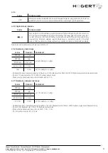
When measuring the resistance in a 99.99 M field, in some cases it will take several seconds to stabilise the reading. This is
normal for measurements with high resistance.
In capacitive measurement mode, „OL” will be displayed when the maximum range is exceeded.
Measuring a large capacitor usually takes several seconds.
Before measuring the capacitor, it is necessary to release the residual charge, which is particularly important for a high volta-
ge capacitor to avoid damage to the meter and personal hazards.
5-3. AC and DC current measurement
Do not try to measure the current in a circuit when the voltage between the voltage in the open circuit and earth exceeds
250 V. Burning the fuse during measurement may cause damage to the meter or personal injury.
When the fuse is disconnected, to avoid damage to the meter or equipment, replace the fuse with the same one before
the measurement. Use the correct input socket and function field for measurement. When the probe is connected to a
current input socket, do not connect the probe tip to any circuit in parallel mode.
1. Disconnect the power supply to the tested circuit. Discharge all high voltage capacitors in the circuit being tested.
2. Turn the rotary switch to the appropriate current field. Use the SEL button to select the DC or AC measurement mode.
3. Insert the black probe into the „COM” input socket and the red probe into the corresponding power input socket.
4. Disconnect the circuit being tested. Connect the black probe to the low potential end of the circuit which has been disconnected
and connect the red probe to the high potential end of the circuit which has been disconnected. (Reversing the probes will give
a negative reading, but will not damage the meter.)
5. Turn on the power supply of the circuit being tested, and then the displayed reading. If the display only shows „OL”, it means that
the input signal is out of range.
6. Cut off the power to the circuit being tested. Discharge all high voltage capacitors. Remove the meter probes and restore the
circuit to its original state
Note: When measuring a large current of 5-10 A, the switch-on time should not exceed 10 seconds to avoid unstable test data
due to heat.
In case of multiple measurements, the interval between two measurements should be 3-5 minutes.
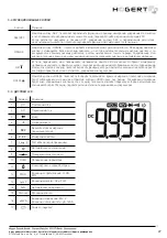
5-4. Continuity and diode test
To avoid damage to the meter or the equipment under test, it is necessary to disconnect the power supply to the circuit
under test and discharge all high voltage capacitors before measuring the diodes.
1. Set the rotary switch to
and connect the probe ends to both ends of the measured object.
2. Connect the black probe to the „COM” input socket and the red probe to the „V” input socket.
3. If the resistance of the measured object is less than 30 ohms, the meter will automatically switch to the Continuity field. Green
indicator on/off light up and the buzzer sounds, indicating that both points are connected and the LCD shows the resistance
value.
4. If the measured object is a diode, the meter will automatically switch to the diode field when it is in a continuous wire and the
LCD screen displays the approximate voltage of the conductive diodes. When the diode is in an open circuit or in reverse polarity,
„OL” will appear on the screen. The normal diode in the circuit should still produce a voltage drop of 0.5 V to 0.8 V. However, the
readout of the return deviation is different from the resistance of other channels between the two probes.
5-5. Live wire test
1. Set the rotary switch in the Live field. The screen displays „----”.
2. Connect the red probe only to the V input socket.
3. Connect the red tip of the probe to the power supply socket L or near a live cable. If the meter detects AC voltage, the LIVE
message will appear on the screen; the two red diodes on the upper right side of the panel will light up, and a buzzer will sound,
indicating that the cable is live.
5-6. NCV test
Detection performance may be affected by factors such as the seat design, thickness and type of insulation. Even if it is
not indicated as LIVE, voltage may still be there. Do not rely solely on a non-contact voltage detector to determine
whether there is voltage on the wire.
When the input voltage is applied to the input terminal of the meter, the voltage detection indicator may light up due to the presen-
ce of induced voltage. But sources of interference in the external environment (such as flashlights, motors, etc.) can accidentally
trigger non-contact voltage detection.
1. Set the function range switch in the NCV field. To determine the presence of alternating voltage or electromagnetic field on an
object, place the probe with the „NCV” sign on the front of the meter near the object.
2. When AC voltage is detected, the screen, NCV indicator and buzzer simultaneously indicate the voltage level. When the induced
voltage is low, the display shows „--L”. The green diode on the left side of the NCV indicator lights up and the buzzer issues
a continuous alarm.
3. When the induced voltage is high, the display shows „--H”. The two red LED diodes on the left side of the NCV indicator light up
and the buzzer emits an alarm continuously at a higher frequency.


