27
Operation manual geodyna 2350 - 9413 126
Entry of balancing mode and wheel size
49
0
1
3
2
X
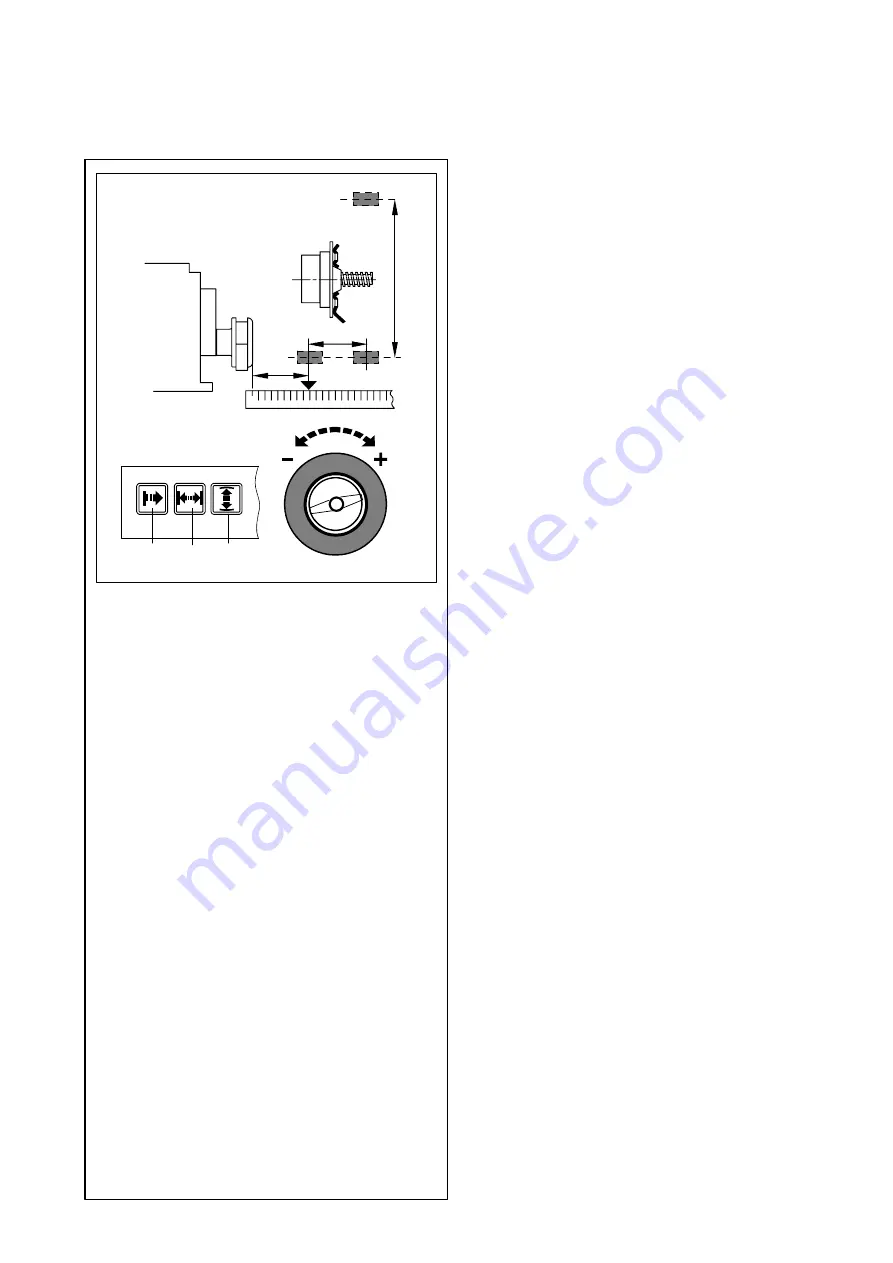
7.2.7 Special balancing operations
If none of the programmable balancing modes can be used:
D
Measure the distance and the actual correction dimen-
sions (center of gravity of balance weight to be attached)
directly on the wheel
(Fig. 49)
.
D
Press and hold the key
(Fig. 49, item 1-3)
and rotate the
wheel to set the values in mm.
D
Release the key as soon as the desired value is read out.
7.2.8 Input for display of static unbalance
For wheels which should only be balanced statically, only the
correction diameter has to be entered.
Input is made as for standard wheels.
D
Press and hold the diameter key and rotate the wheel to
set the diameter values.
D
Release the key as soon as the desired value is read out.
7.2.9 Store wheel profiles
Wheel profiles permit the storage of values for wheels that are
balanced frequently so that the wheel data need not be entered
again and again. This function is particularly useful for shops
that frequently handle the same wheel types.
It is possible to store up to 4 wheel profiles via code
C18
and to
select previously stored profiles via code
C17
(see § 10.
Changing modes of operation).
The following values are stored:
-
Wheel dimensions
-
Values measured with the gauge arm
-
Weight positions
-
Positions for relocation
D
Press and hold OPERATOR key (on bottom).
RCL comes up in the left-hand section of the display and
1 comes up in the right-hand section for the first wheel
profile to be stored. Keep the key pressed on bottom and
rotate the wheel. Profiles 2 through 4 are read out in the
right-hand display. The stored wheel profile is entered
once the key is released.
If a wheel profile is to be stored, keep on pressing the key
after the RCL readings have come up and continue rotat-
ing the wheel. Now STO (store) comes up in the left-hand
display, and No. 1 through 4 can be set in the right-hand
display by rotating the wheel. The current profile is stored
once the key is released.
7.2.10 Correction of inputs after measurement
Upon operation of the FINE key the electronic unit accepts the
new input, processes it and then reads out the corrected
measured data without need to repeat the measuring run.
Содержание Geodyna 2350
Страница 1: ...Operation manual Car wheel balancer geodyna 2350 Hofmann Werkstatt Technik â ...
Страница 61: ...61 Operation manual geodyna 2350 9413 126 16 Electrical diagram ...
Страница 62: ...62 Operation manual geodyna 2350 9413 126 Notes ...
Страница 63: ...63 Operation manual geodyna 2350 9413 126 Notes ...


