background image

16

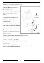
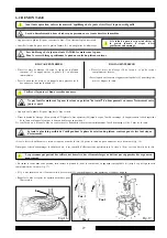
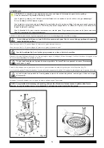
5.5.2 Montaggio e collegamento serbatoio aria per GT

Fissare il serbatoio sul retro della carcassa con le
apposite viti (1)

Smontare il pannello laterale

Fare passare il tubo (2), situato all'interno della carcas-
sa, nel foro posto sul retro della stessa.

Avvitare il tubo (2) al serbatoio tramite l'apposito
raccordo.

5.2.2 Mounting and connecting the GT-tank

Fix the tank on the back side of the machine body through
the proper screws (1).

Demount the side panel.

Let the hose (2), situated inside the machine body, pass
through the hole on the back side of the body.

Tighten  the hose (2) to the tank through the proper union.

5.2.2 Montage et branchement du réservoir d'air pour

GT

Fixer le réservoir sur la partie arrière du bâti moyennant les vis
appropriées (1).

Démonter le panneau lateral.

Laisser passer le tuyau (2), qui se trouve à l'intérieur du bâti, par le trou arrièr au bâti même.

Visser le tuyau (2) au réservoir moyennant le raccord approprié.

5.2.2 Montage und Verbindung von GT-Luftbehälter

Behälter auf Hinterseite der Maschine durch die dazu bestimmten Schrauben (1) befestigen.

Seitenpanel abmontieren.

Schlauch (2), der sich innerhalb der Maschine findet, durch Loch aur Hinterseite der Maschine schieben lassen.

Schlauch (2) an der dazu bestimmten Verschraubung befestigen.

Fig. 10

1

2

Содержание megamount 601

Страница 1: ...enzione Installation operation and maintenance guide Manuel d installation d utilisation et d entretien Installation bedienung und wartung Smontagomme Automatico Démonte pneus Automatique Automatic Tyre Changer Automatisches reifenmontiërgerat Ed 03 02 ...

Страница 2: ... as well as to the following norms ainsi qu aux normes suivantes und folgender Vorschrift gemäß Henndorf 17 06 02 Il modello della presente dichiarazione è conforme a quanto previsto nella Norma EN 45014 The model of present declaration is in conformity with directive EN 45014 Le modèle de cette déclaration est conforme à la Norme EN 45014 Das Modell dieser Erklärung übereinstimmt mit der Bestimmu...

Страница 3: ...3 12 TABELLA GUASTI RIMEDI Pag 47 13 DATITECNICI Pag 49 14 SCHEMIELETTRICIEPNEUMATICI Pag 50 Indice Generale General Index INTRODUCTION Page 5 1 DESCRIPTION OF THE MACHINE Page 7 Danger and prohibition warning signs Page 8 2 GENERAL Page 9 2 1 Intended use Page 9 2 2 General safety precautions Page 10 3 TRANSPORT Page 11 4 UNPACKING Page 11 5 INSTALLATION Page 12 5 1 Space required Page 12 5 2 Par...

Страница 4: ...NN CAUSES REMEDES Page 47 13 DONNES TECHNIQUES Page 49 14 SCHEMAS ELECTRIQUE ET PNEUMATIQUE Page 50 EINFÜHRUNG Seite 5 1 BESCHREIBUNG DER MASCHINE Seite 7 Gefahrenhinweise und Verbote Seite 8 2 ALLGEMEINES Seite 9 2 1 Verwendungszweck Seite 9 2 2 Allgemeine Sicherheitsvorschriften Seite 10 3 TRANSPORT Seite 11 4 AUSPACKEN DER MASCHINE Seite 11 5 INSTALLATION Seite 13 5 1 Platzbedarf Seite 13 5 2 B...

Страница 5: ...at shown on the plate fixed to the tyre changer the latter should be taken as correct INTRODUCTION Nous vous remercions d avoir choisi un produit de la ligne des démonte pneus Automatiques La réalisation de ces machines a été soignée dans les moindres détails pour vous offrir des produits de qualité Pour un fonctionnement correct et une longue durée il suffit d observer les instructions de ce manu...

Страница 6: ...ce Conserver très soigneusement ce manuel pour le consulter si nécessaire Bewahren Sie dieses Handbuch sorgfältig auf damit Sie es jederzeit wieder konsultieren können Anm ein Teil der in diesem Buch enthaltenen Abbildungen ist von Prototypphotographien gezogen Es ist deshalb möglich daß einige Maschinenteile von Abbildung serienmäßig verschieden hergestellt werden NOTA Parte delle illustrazioni c...

Страница 7: ...edal V Clamp control pedal Z Reverser control pedal with 2 speed H Tilting arm pedal Y Turntable K Locking button G Mors de blocage I Tête de montage L Pistolet de gonflage M Barre de montage N Bras horizontal P Bras vertical Q Raccord air comprimé R Détalonneur S Supports de roue T Levier démonte pneus U Pédale de commande du détalonneur V Pédale de commande des mors Z Pédale de commande de l inv...

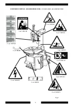
Страница 8: ...TENZE DI PERICOLO DANGER WARNING SIGNS AVIS DE DANGER GEFAHRENHINWEISE Cod 3005413 Cod 3005416 Cod 3005415 Cod 3005410 Fig 2 Cod 3005414 Cod 3001104 Cod 3005742 Cod 3005411 Cod 3006367 Cod 3000048 Cod 3000798 ...

Страница 9: ...yre changer for purposes other than those specified in this manual and therefore inappropriate incorrect and unreasonable 2 GENERALITES 2 1 DESTINATION Le démonte pneus semi automatique a été projeté et réalisé exclusivement pour le démontage et le montage des pneus des sur les jantes avec dimensions de 12 à 22 et diamètre max de 1000 mm Toute autre utilisation doit être considérée impropre et don...

Страница 10: ...he manufacturer using the codes given on page 8 2 2 NORMES GENERALES DE SECURITE L utilisation du démonte pneus est permise exclusivement à du personnel spécialisé expressément formé et autorisé Le constructeur n est pas responsable des dommages causés par les appareils qui ont été modifiés sans son autorisation préalable La garantie est immédiatement nulle si des modifications ou des transformati...

Страница 11: ...eten Gabelstapler angehoben und transportiert werden wobei die Gabeln an den in Abb 3 angegebenen Punkten einzuschieben sind Fig 3 Standard Kg 255 GT Kg 261 4 DISIMBALLO Togliere il cartone di protezione e il sacchetto in nylon Assicurarsi dell integrità dell apparecchio controllando che non vi siano parti visibilmente danneggiate o mancanti facendo riferimento alla fig 1 In caso di dubbio non uti...

Страница 12: ...me sia del tipo a motore elettrico è proibito l uso in atmosfere esplosive a meno che non si tratti di una apposita versione 5 INSTALLATION 5 1 SPACE REQUIRED When choosing the place of installation be sure that it complies with current safety at work regulations The tyre changer must be connected to the mains electric power supply and the compressed air system It is therefore advisable to install...

Страница 13: ...moins qu il ne s agisse d une version appropriée 5 INSTALLATION 5 1 PLATZBEDARF Bei der Wahl des Aufstellungsortes müssen die gültigen Bestimmungen zur Sicherheit am Arbeitsplatz beachtet werden Das automatische Reifenmontiergerät benötigt Anschlüsse an das Stromnetz und an die Druckluftzufuhr Deshalb ist es ratsam dieMaschine in der Nähe dieser Energiequellen aufzustellen Zudem muss am gewählten ...

Страница 14: ...e la rondella 15 resti dalla parte interna del braccio e la rondella 16 dalla parte esterna Bloccare il tutto avvitando il dado autobloccante 17 sul perno della paletta 1 2 3 4 Fig 5 Fig 6 5 2 PARTS ASSEMBLY 5 2 1 Arms assembly Set the vertical arm into its housing on the machine body as shown in picture 5 Set the back screws 1 the bushes 2 the washers 3 and tighten the nuts 4 Picture 6 Set pin 5 ...

Страница 15: ... Fig 9 A Bloquer le tout en vissant l écrou de sécurité 17 sur l axe de la palette Fig 9 A 5 2 BESTANDTEILENEINBAU 5 2 1 Armeinbau Den senkrechten Arm in die dazu bestimmte Stütze auf der Maschinengehäuse einfügen siehe Abb 5 Die hintere Schrauben 1 die Buchsen 2 sowie die Beilagsscheiben 3 einfügen und die Mutter 4 anziehen Abb 6 Stift 5 mit Beilagsscheibe 6 einfügen um den Kippzylinder mit dem A...

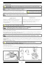
Страница 16: ...back side of the body Tighten the hose 2 to the tank through the proper union 5 2 2 Montage et branchement du réservoir d air pour GT Fixer le réservoir sur la partie arrière du bâti moyennant les vis appropriées 1 Démonter le panneau lateral Laisser passer le tuyau 2 qui se trouve à l intérieur du bâti par le trou arrièr au bâti même Visser le tuyau 2 au réservoir moyennant le raccord approprié 5...

Страница 17: ...machine body Connect the rilsan hose to the union of the pressure limiting device situated on the inflating pedal 5 2 3Montageetbranchementdumanomètre Fixer la boîte manomètre au bras vertical moyennant les vis fournies Laisser passer le tuyau spirale de connexion par le petit trou qui se trouve arrière au bâti Brancher le tuyau rilsan au raccord du limitateur de pression sur la pédale de gonflage...

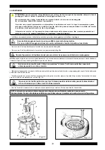
Страница 18: ...hich conforms to the voltage of the machine in compliance with the regulations in force 5 3 MISE EN MARCHE Avant d effectuer les raccordements vérifier que les caractéristiques des installations correspondent à celles demandées par la machine S il faut changer la tension de fonctionnement de la machine intervenir sur le bornier voir schéma électrique Chap 14 Les interventions sur l installation él...

Страница 19: ... il grilletto della pistoletta di gonfiaggio esce aria dalla testina 5 4 OPERATING TESTS When pedal A is pressed down at first position the turntable L should turn in a clockwise direction at low speed When pedal A is pressed down at second position the turntable L should turn in a clockwise direction at high speed When pedal A is pulled up the turntable L should turn in an anticlockwise direction...

Страница 20: ...e bras se débloquent et la tête de montage monte en position hors service En appuyant sur la détente du pistolet de gonflage l air sort 5 4 FUNKTIONSTEST Bei Drücken auf Pedal Z in erster Stellung wird der Zentriertisch Y langsam rechts drehen Bei Drücken auf Pedal Z in zweiter Stellung wird der Zentriertisch Y schnell rechts drehen Bei Drücken auf Pedal Z nach oben wird der Zentriertisch Y langsa...

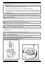
Страница 21: ...rückgerät strömen Wird das Pedal C ganz gedrückt so strömt Luft aus dem Reifenfülldruckgerät und ein starker Luftstrom aus den Düsen die sich an den Spannklauen des Zentriertisches befinden Nell effettuare questa prova non tenere il viso sopra l autocentrante Eventuale sporcizia presente sul piatto potrebbe colpire gli occhi di chi opera Fare attenzione anche a non premere accidentalmente il pedal...

Страница 22: ...wendung von Sonderstoff sowie Kohlen oder Magnesium hergestellt Zum Einspannen solcher Felgen ist es nötig die Satz von Motorradräderadaptern Kode Nr 2008632 zu verwenden und den vom Zentriertisch getriebenen Druck zu max 5 Bar zu begrenzen Auf diese Weise wird es vermeidet die Felgen zu beschädigen o verformen Sollte Ihre Montiermaschine mit Druckregler nicht versehen sein so wird es empfohlen Sa...

Страница 23: ...nte aperte potrebbe causare lo schiacciamenot delle mani Accertarsi che siano chiuse e non tenere mai le mani sui fianchi del pneumatico 6 1 BREAKING THE BEAD Check that the tyre is deflated If not deflate it Close the turntable clamps completely Position the wheel against the rubber stops on the right side of the tyre changer S Position the bead breaker blade R against the tyre bead at a distance...

Страница 24: ...nrand lassen Abb 15 und darauf beachten daß der Abdrücker fehlerfrei auf den Reifen und nicht auf die Felge wirkt Pedal U drücken und das Abdrückblatt betätigen loslassen wenn das Blatt am Laufende angelangt ist Reifen leicht drehen und den Vorgang beidseitig auf dem gesamten Felgenumfang wiederholen bis sich der Wulst sich vollständig von der Felge gelöst hat L opération de décollage doit être ex...

Страница 25: ...azione di ribaltamento del palo accertarsi che nessuno sosti dietro lo smontagomme Assicurarsi che il cerchio sia ben agganciato alle griffe Richiamare il palo P premendo il pedale H Posizionare il pulsante di bloccaggio K in posizione 2 Spostare il braccio operante M fino ad appoggiare la torretta I sul bordo superiore del cerchio e bloccare il tutto premendo il pulsante di bloccaggio in pos 1 In...

Страница 26: ...ng between rim and mounting tool Return the arm P by pressing the pedal H Set the locking button K in position 2 Move th operating arm M until the mounting tool I rests on the rim upper edge Then lock everything by setting the locking button in position 1 In this way the arm gets locked both in a vertical and in a horizontal direction while the mounting tool I is moved automatically of about 2 mm ...

Страница 27: ...du bras pourrait en causer l écrasement entre jante et outil Appuyer sur la pédale G pour rappeler le bras vertical Placer le bouton de blocage K en position 2 Déplacer le bras opérateur M jusqu à ce que l outil de montage I s appuie contre le bord supérieur de la jante et bloquer le tout par le bouton de blocage en position 1 De cette façon on a bloqué le bras en sens vertical et horizontal et dé...

Страница 28: ...ingen Bedienungsarm M verstellen bis sich das Montierwerkzeug I an obere Felgenkante lehnt Sicherungsknopf auf Position 1 jetzt bringen damit alles blockiert wird Auf diese Weise wird der Arm senkrecht und waagerecht blockiert und das Montierwerkzeug I automatisch von 2 mm aus Felge entfernt Bei Tischdrehung Hände und Körper möglichst fern vom Montierwerkzeug halten um Quetschungen zu verhüten Mit...

Страница 29: ...il braccio operante basta ribaltare e richiamare il palo P con i bracci già bloccati in posizione di lavoro Manipolare il pneumatico in modoche il tallone passi sotto la parte anteriore della torretta e venga appoggiato sopra il bordo della parte posteriore della torretta stessa Tenendo premuto con le mani il tallone del pneumatico nella gola del cerchio premere il pedale Z per ruotare l autocentr...

Страница 30: ...far as possible from the tool arm when the table top is turning Fig 19 Fig 18 NOTE Demounting and mounting are always done with the clockwise turntable rotation Anticlockwise rotation is used only to correct operator s errors or if the turntable stalls 6 3 MOUNTING THE TYRE WARNING This checking of tyre and rim is of th utmost importance to prevent tyre explosion during the inflating operations Be...

Страница 31: ...ommagements et faciliter le montage Pour des roues de 10 à 22 pouces bloquer la jante avec la partie intérieure des mors Pour des roues de 12 à 24 pouces bloquer la jante avec la partie extérieure des mors Lors du basculement du bras s assûrer que personne ne se trouve derrière la machine Ne pas tenir les mains sur le pneu le retour en position de travail du bras pourrait en causer l écrasement en...

Страница 32: ...wohl bei Ansicht als auch beim Antasten keinen Mangel vorweist und daß das Leinen nicht beschädigt ist Im Mangelfall den Reifen NICHT montieren die Felge keine Beule oder Verformung vorweist Besonders bei Alu Felgen können die Beulen innere Mikrobrüche verursachen die mit bloßem Auge nicht sichtbar sind und die die Solidität der Felge gefährden und eine Gefahr bei Aufpumpenphase darstellen können ...

Страница 33: ...ono forniti con pistoletta di gonfiaggio Per gonfiare un pneumatico procedere come segue Collegare il raccordo della pistoletta alla valvola del pneumatico Verificare ulteriormente l esatta corrispondenza dei diametri di cerchio e pneumatico Verificare che cerchio e pneumatico siano sufficientemente lubrificati eventualmente lubrificare Premere e rilasciare con frequenza il grilletto della pistole...

Страница 34: ... tyre changers are supplied with an airline gauge To inflate a tyre proceed as follows Connect the airline gauge fitting to the tyre valve Make a last check to be certain that tyre and rim diameter correspond Check to be certain that rim and beads are sufficiently lubricated If necessary lubricate some more Seat the beads with short jets of air Between air jets check the air pressure on the inflat...

Страница 35: ...ccord du pistolet sur la valve du pneu Vérifier encore une fois que les diamètres de la jante et du pneumatique correspondent Vérifier que la jante et le pneumatique sont suffisamment lubrifiés éventuellement lubrifier Talonner en introduisant l air par petits jets et vérifier continuellement dans les intervalles la pression sur le manomètre du pistolet jusqu à ce que les talons sont à leur place ...

Страница 36: ...ifens wie folgt vorgehen Anschlußstutzen der Druckluftpistole ans Reifenventil anschließen Sicherstelen daß Durchmesser von Felge und Reifen zuinander passen Sicherstellen daß Felge und Reifen ausreichend geschmiert sind Ggf erneut einstreichen Den Reifenwulst aufziehen indem man kurzfristig Luft einbläst und dazwischen immer die Luftdruck auf dem Manometer der Pistole mißt bis die Reifenwülste ri...

Страница 37: ... aria dagli ugelli posti sulle griffe In questa fase della lavorazione si possono avere livelli di rumore attorno agli 85 db A E consigliabile utilizzare una protezione anti rumore Collegare il raccordo del gonfiatore alla valvola del pneumatico Verificare ulteriormente l esatta corrispondenza dei diametri di cerchio e pneumatico Verificare che cerchio e pneumatico siano sufficientemente lubrifica...

Страница 38: ... the rim then press pedal all the way down C Fig 21 A strong jet of air will be released through the nozzles in the slides and this will help the bead seal Release the tyre set the pedal in the intermediate position B Fig 21 and continue to inflate the tyre with short jets of air and constantly checking the pressure between air jets until the required pressure has been reached EXPLOSION HAZARD Nev...

Страница 39: ... à fond la pédale C Fig 21 Un jet d air puissant sortirà des buses qui se trouvent sur les support coulissants en permettant le tallonage Relâcher le pneumatique et soulever doucement le pied pour remettre la pédale de gonflage dans la position intermédiarie B Fig 21 Continuer en introduisant de l air par petites doses et en vérifiant la pression dans les intervalles jusqu à atteindre la pression ...

Страница 40: ... den Öffnungen in den gleitfähigen Spannklauen aus und hilft beim Aufziehen des Reifens Den Reifen loslassen und den Fuß auf dem Pedal leicht anheben damit dieses in die Zwischenstellung bringen B Abb 21 Weitermachen und Luft einblasen wobei man zwischendurch immer den Luftdruck mißt bis der gewünschte Reifendruck erreicht ist EXPOSITIONSGEFAHR Beim Aufpumpen darf Druckwert von 3 5 bar 51 PSI nie ...

Страница 41: ...s à l endroit choisi NB L endroit choisi pour repositionner le démonte pneus doit être conforme aux normes européennes pour la prévention des accidents du travail 8 NEUPOSITIONIEREN Soll das Reifenmontiergerät neu positioniert werden muß ein Gabelstapler verwendet werden Druckluft und Stromzufuhr unterbrechen Eine Seite der Maschine leicht anheben Gabeln des Hubwagens unter den Sockel einführen un...

Страница 42: ...econdo le leggi nazionali vigenti Raccogliere l olio e smaltirlo negli appositi centri secondo le leggi nazionali vigenti Rottamare il resto come materiale ferroso 10 SCRAPPING If you decide to scrap the machine be sure to make it inoperative by disconnecting it from all sources of power Remove all NON ferrous materials and dispose of them as prescribed by national law Collect the oil and dispose ...

Страница 43: ...pneumatic supplies Moreover it is necessary to break the bead loadless 3 4 times in order to let the air in pressure go out of the circuit Defective parts must be replaced exclusively by expert personnel using the manufacturer s spare parts Removing or tampering with safety devices pressure limiting and regulating valves represents a contravention of European Safety Standards In particular The MAN...

Страница 44: ...VG 32 come ad esempio ESSO Febis K32 MOBIL Vacouline Oil 1405 KLUBER Airpress 32 fig 22 Controllare che ogni 3 4 pressioni sul pedale U cada una goccia di olio nella tazza F In caso contrario regolare l apposita vite D fig 22 NOTA Dopo i primi 20 gg di lavoro stringere nuovamente le viti di serraggio delle griffe e degli scorrevoli del piatto autocentrante fig 23 NOTA Se la macchina accusasse un c...

Страница 45: ...NTRETIEN Toutes les semaines nettoyer le plateau tournant avec du mazout pour éviter la formation de saleté et graisser les glissières des mors Tous les mois vérifier le niveau de l huile dans le réservoir du graisseur Si nécessaire ajouter de l huile en dévissant le reservoir F Rajouter en utilisant de l huile pour installation pneumatiques de classe ISO HG à viscosité ISO VG 32 par exemple ESSO ...

Страница 46: ...ke Seitenwand des Reifenmontiergerätes abnehmen hierzu die 4 Blockierungsschrauben lösen Motorriemen mittels Regler X an der Motorhalterung ziehen Abb 24 WICHTIG Falls die Blockierungsplatte des Arms eingestellt werden muß weil sich Werkzeug oder Kipparm nicht blockieren oder von den nötigen 2mm nicht heben lassen wie in Abbildung 25 beschrieben vorgehen WICHTIG Solltet das Montierwerkzeug waagrec...

Страница 47: ...ie cassée La remplacer Inverseur de tours cassé Le remplacer Problèmes au moteur Contrôler les fils dans la fiche dans le moteur ou dans la prise Remplacer le moteur Riemen gerissen Riemen auswechseln Wendegetriebe defekt Wendegetriebe auswechseln Probleme im Motor Überprüfen ob sich eventuell Drähte im Stecker im Motor oder in der Steckdose gelöst haben Motor auswechseln Autocentrante si blocca T...

Страница 48: ...que de blocage non réglée ou défectueuse Régler ou remplacer la plaque Chap 11 fig 25 26 Vis de blocage du plateau tournant desserrée Serrer la vis Blockierungsplatte nicht eingestellt oder defekt Blockierungsplatte einstellen oder auswechseln Kap 11 Abb 25 26 Blockierungsschraube des Zentriertisches locker Schraube anziehen I pedali si bloccano fuori posizione Pedals lock out of working position ...

Страница 49: ...e r o m u r o l l e v i L s n o i t i d n o c g n i k r o w n i l e v e l e s i o N A B d 0 7 S E U Q I N H C E T S E E N N O D S E U Q I N H C E T S E E N N O D S E U Q I N H C E T S E E N N O D S E U Q I N H C E T S E E N N O D S E U Q I N H C E T S E E N N O D N E T A D E H C S I N H C E T N E T A D E H C S I N H C E T N E T A D E H C S I N H C E T N E T A D E H C S I N H C E T N E T A D E H C ...

Страница 50: ...X 6 5 X X X X X 4 3 X X X X X 2 1 X X X X X i t t a t n o C i t t a t n o C i t t a t n o C i t t a t n o C i t t a t n o C s t c a t n o C L L L L L 0 0 0 0 0 R R R R R 230V 1PH 400V 3PH 2 SPEED 6 6 6 6 6 3 2 4 2 1 2 2 2 5 5 5 5 5 9 1 0 2 7 1 8 1 4 4 4 4 4 5 1 6 1 3 1 4 1 3 3 3 3 3 1 1 2 1 9 0 1 2 2 2 2 2 7 8 5 6 1 1 1 1 1 3 4 1 2 2 L 1 L 0 1 R Elements Contacts ...

Страница 51: ...51 110V 1PH ...

Страница 52: ...ndro blocc braccio oper 14 Rubinetto 15 Valvola di sicurezza 16 Cilindro ribaltamento palo 17 Valvola ribaltamento palo 18 Cilindro blocc braccio orizz 19 Cilindro sollevamento braccio operante 1 Lubricator 2 1 8 Silencer 3 Turntable valve 4 Inflating gauge 5 Pressure regulator 6 1 4 Quick relief valve 7 1 4 Silencer 8 Double effect Bead breaker cylinder 9 Turntable cylinder 10 Rotating union 11 B...

Страница 53: ...nflating head 10 Divider 11 Pressure gauge 12 Inflating unit 13 Deflating valve 14 Rotating union 3 Valvola di sicurezza 4 Serbatoio aria 5 Valvola di intallonamento 6 Valvola pedale GT 7 Regolatore di pressione 8 Valvola di sicurezza 9 Testina di gonfiaggio 10 Ripartitore 11 Manometro 12 Unità di gonfiaggio 13 Valvola di sgonfiaggio 14 Raccordo girevole ...

Страница 54: ...2 9 Pressure detector 10 Pressure regulator 11 Safety valve 12 Inflating unit 13 Rotating union 14 Inflating head 1 Rubinetto manuale 2 Regolatore di pressione 3 Valvola di ritegno 4 Valvola di sicurezza 5 Serbatoio 6 Elettrovalvola di intallonamento E3 7 Elettrovalvola di gonfiaggio E1 8 Elettrovalvola di sgonfiaggio E2 9 Sensore di pressione 10 Regolatore di pressione 11 Valvola di sicurezza 12 ...

Страница 55: ...55 ...

Страница 56: ...56 Hofmann Megaplan GmbH Hauptstraße 59 A 5302 Henndorf Austria Telefon 43 6214 646612 Fax 43 6214 646622 ...

Отзывы: