background image

FIRElink-25 – Installation Manual  


Page 31 of 40 

©

 2010 Hochiki Europe (UK) Ltd 

9-5-0-344/ISS4/OCT10 


5.4  Connecting to a PC 

To connect a single stand-alone detector to a PC, connect the PC‘s serial port directly to the detector‘s 9-
way RS232 port, which is situated on the bottom surface of the detector case.  Connections for this cable 
are shown below: 


Содержание FIRElink-25

Страница 1: ...FIRElink 25 Air Sampling System INSTALLATION MANUAL...

Страница 2: ...UK Ltd All rights reserved No part of this document may be reproduced stored in a retrieval system or transmitted in any form or by any means without the prior permission in writing of Hochiki Europe...

Страница 3: ...2 Programmed Isolate 12 2 4 3 Latching Alarms 12 2 4 4 Latching Faults 12 2 4 5 Cascading Alarms 12 2 5 Device Information Tab 13 2 5 1 Device Type 13 2 5 2 Firmware Version 13 2 5 3 Run time Hours 1...

Страница 4: ...T RS485 Detector Network 29 5 3 Connecting a FIRElink 25 to an addressable Fire Panel 29 5 4 Connecting to a PC 31 6 Event Log 32 7 Commissioning 34 7 1 Commissioning Checklist 34 8 Maintenance 35 8 1...

Страница 5: ...ide a consistent level of protection in a very wide range of environments by continuously making minor adjustments to sensitivity The FIRElink range of detectors has proven its worth many times by det...

Страница 6: ...Department to ensure trouble free installation and operation Hochiki Europe UK Limited takes no responsibility for damage or injury occasioned as a result of failing to install or operate the equipme...

Страница 7: ...K Ltd 9 5 0 344 ISS4 OCT10 1 2 Inside the Detector Removable terminal blocks see section 1 3 Filter see section 8 Addressable programmable interface card FIRElink APIC port see section 5 3 Detector ad...

Страница 8: ...Terminal Block Connections Normally closed FAULT relay contacts Normally open FIRE relay contacts FIRElink APIC addressable bus connections for use in conjunction with interface card see sections 4 1...

Страница 9: ...ngs submenu or by clicking on the detector button on remote software toolbar as indicated below The following screen is displayed This window contains all the programmable functions for the FIRElink 2...

Страница 10: ...ty 8 low sensitivity lower probability The default alarm factor is 4 Note The highest sensitivity setting is suitable for clean environmentally controlled environments e g semiconductor manufacturing...

Страница 11: ...ector to initiate FastLearn mode 2 2 7 Auto FastLearn Enable When enabled this function ensures that if the detector is powered off for any reason e g for maintenance or to be moved to a new area a Fa...

Страница 12: ...e 2 4 Alarm Actions Tab 2 4 1 Remote Functions Remote Input subgroup These functions have no current use on the FIRElink 25 but are reserved for future expansion purposes 2 4 2 Programmed Isolate When...

Страница 13: ...oblem can be found in the event log See section 6 Event Log for further details 2 5 5 Device Text This function has no current use on the FIRElink 25 but is reserved for future expansion purposes 2 6...

Страница 14: ...is programmable from 30 to 240 seconds The flow level needs to be above the high flow threshold or below the low flow threshold throughout the delay period for a fault to be generated NOTE When settin...

Страница 15: ...s 20 minutes 16 Flow Recording 5 minutes 50 minutes 17 Flow Recording 10 minutes 100 minutes 18 Flow Recording 20 minutes 200 minutes 19 Flow Recording 50 minutes 500 minutes In the above table the sh...

Страница 16: ...larm factor other than the default is required for the protected area this will need to be re entered Section 2 2 4 gives details of the ClassiFire alarm factors 2 9 Other Remote Software Features 2 9...

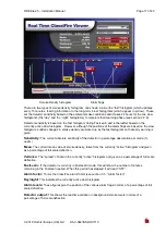
Страница 17: ...icked up by the fast histogram so that early warning is given Sensitivity The current absolute sensitivity of the detector in percentage obscuration per metre obs m Mean The current mean value of smok...

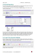
Страница 18: ...indow shown at the bottom left updates to show the date and time detector level and alarm level of the relevant period The File menu option in the chart recording window allows the chart recording to...

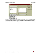
Страница 19: ...ISS4 OCT10 A list will appear of all detector settings files stored on the current drive As a special case if desiring to recall the factory default settings there is a file named default dfs in the r...

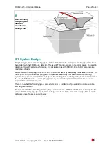
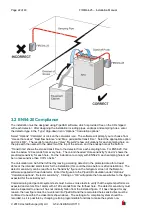
Страница 20: ...um sampling pipe length is reduced to 25 metres Although by no means essential it must be recommended that if in doubt PipeCAD be used to ensure that transit times balance of suction and individual sa...

Страница 21: ...y be expected to travel Do not expect ceiling mounted sampling points to operate satisfactorily if air flow from air conditioning systems keeps the cool smoke from an incipient fire reaching from reac...

Страница 22: ...to comply with EN54 20 each sampling hole must be no less sensitive than 0 31 obs m The calculation can be further refined by leaving a working detector in the protected area for at least 24hrs at th...

Страница 23: ...mended that the system is retested if continuing compliance is in any doubt The results should be verified at installation by entering the installed detector s Fire 1 sensitivity as indicated in the r...

Страница 24: ...ure zone as the sampling holes Sampling holes should be free from burrs and swarf All signal cables must be screened and must be of a suitable type The specific type of cable will normally depend upon...

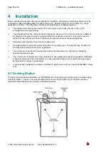
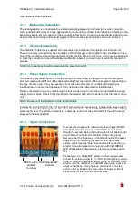
Страница 25: ...firmly held when the cable gland is fully tightened Remove the detector cover by unfastening the four screws at the front of the unit and detach the power supply terminal block This is at the top left...

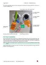
Страница 26: ...ation Once the power and signal connections are made slide the detector body up into the docking station and fasten it into position using the M4 pan head screws provided Slot the power and signal ter...

Страница 27: ...FIRElink 25 Installation Manual Page 27 of 40 2010 Hochiki Europe UK Ltd 9 5 0 344 ISS4 OCT10 Dock Fixing Screws Cover Fixing Screws Cover Fixing Screws...

Страница 28: ...t are likely to be used 5 1 Setting the Detector Address In order to identify itself to the PC Command Module or fire panel each detector needs to have a unique address ranging from 1 to 127 The detec...

Страница 29: ...f this is done it is recommended that bare wire joints be insulated to prevent possible shorting of the data bus which will cause a drop out of data on the SenseNET bus In the above example there coul...

Страница 30: ...eed to be made are on the FIRElink APIC address DIP switches The start loop address Is entered on SW1 and the end loop address on SW2 In the case of a single FIRElink 25 the start and end addresses wi...

Страница 31: ...d 9 5 0 344 ISS4 OCT10 5 4 Connecting to a PC To connect a single stand alone detector to a PC connect the PC s serial port directly to the detector s 9 way RS232 port which is situated on the bottom...

Страница 32: ...he detector stores an internal log of the last 200 events and this can either be viewed on a PC screen or downloaded to disk by use of the remote control software When the event log is full 200 events...

Страница 33: ...ame Print prints the event log to a connected printer Filter clicking on this option displays the following screen This allows the user to limit the information printed or viewed on the PC screen For...

Страница 34: ...detector visually check all cabling to ensure correct connection If wire identification is not immediately clear for example by use of different coloured wires or wire identification sleeves an electr...

Страница 35: ...ection of flow arrow printed on the carton duplicates that on the Direction of flow label beside the filter slot As dust contained in the dust separators may expose maintenance personnel to a Nuisance...

Страница 36: ...the fault will be indicated in the Status column Scan Reads in the status of all connected detectors Read Button This brings up a display of the detector output and flow rate which updates in real tim...

Страница 37: ...tor has either had a 24 hour learning period or that it has been placed in demonstration mode 9 3 Low Mean Output Check that the filter does not require changing see section 2 8 3 and that the air ple...

Страница 38: ...ipe giving the error is not blocked Check that the low flow fault threshold is not set too high see section 2 7 3 9 5 2 High Flow Error Messages Check that the pipe is pushed home into the inlet and i...

Страница 39: ...erating parameters of the detector temperature 10 to 60 C humidity 0 90 non condensing DON T Forget to set the appropriate ClassiFire alarm factor for the area to be detected Forget to set the Detecto...

Страница 40: ...ring mass detection Particle Sensitivity Range 0 0003 m to 10 m Current Consumption 250mA Relay Contact Rating 500mA 30Vd c Maximum Sampling Pipe Length 50 metres total see section 3 Design Limitation...

Отзывы: