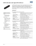
HOBO U20L Water Level Logger (U20L-0x) Manual
1-800-LOGGERS 3
www.onsetcomp.com
Logger Operation
HOBOware Pro software is required for logger operation. Using
a reference water level, HOBOware Pro automatically converts
pressure readings into water level readings (see
Barometric
Compensation
for more detail). The software also supports
compensation for temperature, fluid density, and barometric
pressure.
An LED in the communications window of the logger confirms
logger operation. When the logger is logging, the LED blinks
once every one to four seconds (the shorter the logging
interval, the faster the LED blinks). The LED also blinks when the
logger is recording a sample. When the logger is awaiting a start
because it was configured to start “At Interval,” “On
Date/Time,” or “Using Coupler,” the LED blinks once every eight
seconds until logging begins.
The logger can record two types of data: samples and events.
Samples are the sensor measurements recorded at each logging
interval (for example, the pressure every minute). Events are
independent occurrences triggered by a logger activity, such as
Bad Battery or Host Connected. Events help you determine
what was happening while the logger was logging.
Barometric Compensation
The logger records absolute pressure, which is later converted
to water level readings by HOBOware Pro software. In this
application, absolute pressure includes atmospheric pressure
and water head. Atmospheric pressure is nominally 100 kPa
(14.5 psi) at sea level, but it changes with weather and altitude.
Left uncompensated, barometric variations could result in
errors of 0.6 m (2 ft) or more.
To compensate for barometric pressure changes, you can use
another HOBO U20L Water Level logger as a barometric
reference. The barometric reference is typically deployed in the
same well or at the same location as the water level of interest,
but rather than being placed in the water column, it is deployed
above the water in air.
Barometric pressure readings are consistent across a region
(except during fast-moving weather events), so you can
generally use barometric pressure readings that are taken
within 15 km (10 miles) of the logger or more without
significantly degrading the accuracy of the compensation.
Therefore, one HOBO U20L or U20 Water Level logger or
weather station (HOBO U30 recommended) can be used to
compensate all the water level loggers in an area. The U20L-01
model with its 0–9m (0–30 ft) range or the U20L-04 with its
0–4 m (0–13 ft) range are both good barometric references due
to their smaller range and temperature-compensated accuracy.
HOBOware Pro includes a Barometric Compensation Assistant
for easy and accurate barometric compensation. See
Processing
Water Level Data using Barometric Pressure Data
for more
details.
Calibration
The pressure sensor in each HOBO U20L Water Level logger is
individually calibrated. During calibration, raw pressure sensor
data is collected at multiple pressures and temperatures over
the calibrated range of the logger (see the specifications table).
This data is used to generate calibration coefficients that are
stored in the logger’s non-volatile memory. The calibration
coefficients are then checked to be sure that the logger meets
its stated accuracy over the calibrated range.
The pressure sensor can be used at pressures and temperatures
that are outside of the calibrated range, but the accuracy
cannot be guaranteed.
Important:
Never exceed the burst pressure of the sensor!
Connecting the Logger to a Computer
The HOBO Water Level Logger requires a coupler (COUPLER2-C)
and Optic Base Station (BASE-U-4) or HOBO Waterproof Shuttle
(U-DTW-1, firmware version 3.2.0 or later) to connect to the
computer. The optical interface allows the logger to be
offloaded without breaking the integrity of the seals. The USB
compatibility allows for easy setup and fast downloads.
Important:
USB communications may not function properly at
temperatures below 0°C (32°F) or above 50°C (122°F).
Sensor face; make
sure sensor face is in
the water when
deploying the logger
(the sensor is located
inside the logger case
as represented by
dashed lines in this
diagram)
Removable end
cap covering
communications
window
Bump for
alignment
with coupler
Mounting
hole
16.8 mm (0.66 in.)


