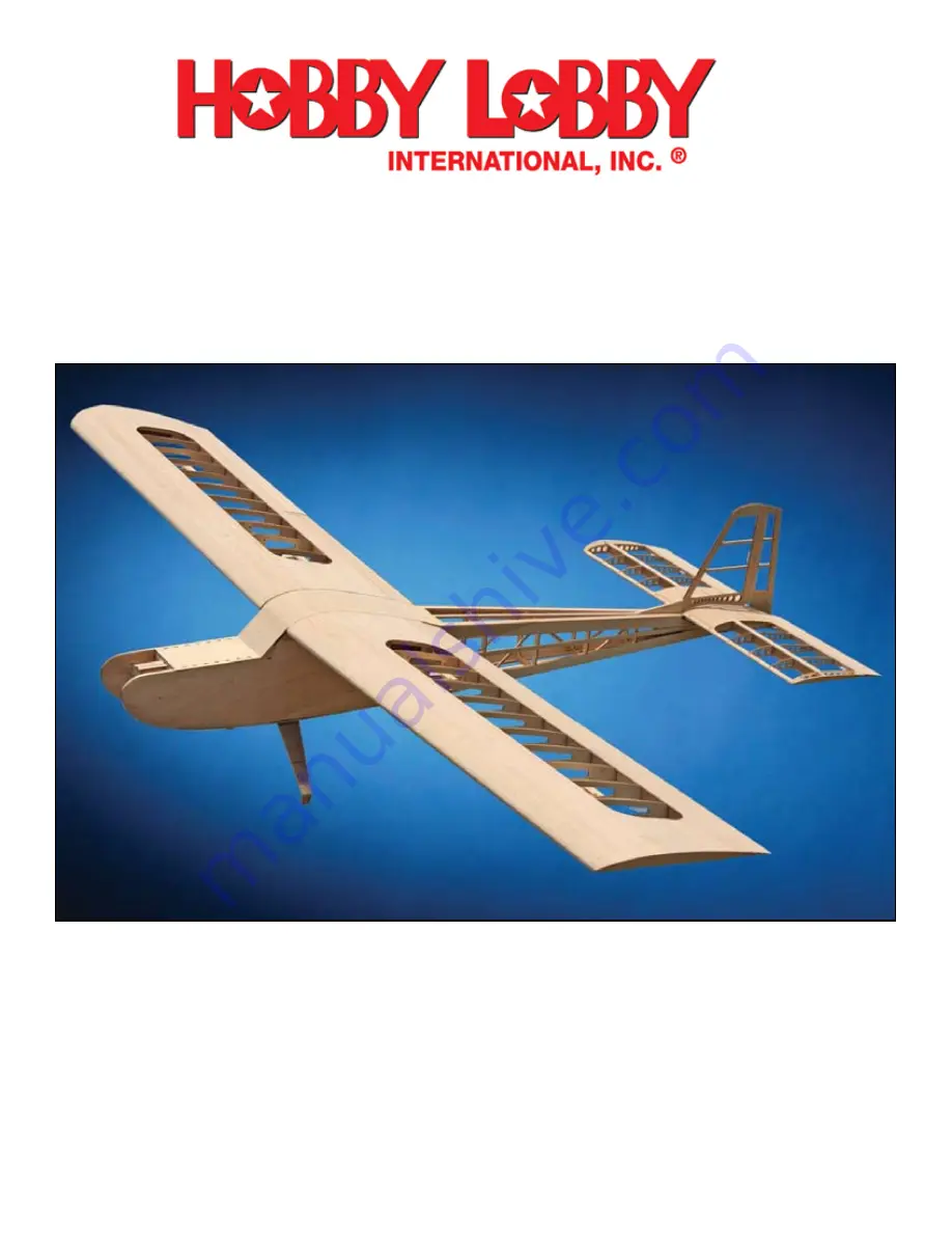
SENIOR TELEMASTER KIT
TEL1600
MADE IN THE USA
Hobby Lobby International
5614 Franklin Pike Circle
Brentwood TN 37027 USA
Phone 866-512-1444
TEL1600 -REV 1.13
Страница 1: ...SENIOR TELEMASTER KIT TEL1600 MADE IN THE USA Hobby Lobby International 5614 Franklin Pike Circle Brentwood TN 37027 USA Phone 866 512 1444 TEL1600 REV 1 13...
Страница 2: ......
Страница 3: ...wever there are times when it is not the best choice They are 1 When you need more time to carefully position a part than a fast setting adhesive will allow 2 When attaching plastic such as a windshie...
Страница 4: ...into the wing This is an example of a left and right handed assembly W1 IN should be facing into the wing Tip Side and W1 OUT should be fac ing toward the fuselage Root Side when the assembly is inst...
Страница 5: ...d accurately Make sure it is fully engaged in the tab of W1 A and flat against the W1 assembly The rib subassemblies should look like this It is best to assembly them all at the same time to avoid err...
Страница 6: ...a 1 piece of triangle stock at the trailing edge Cut and glue pieces of 3 8 triangle stoct to W14 and WT between the leading edge and the gusset and between the gusset and the trailing edge Use a razo...
Страница 7: ...nstalling the leading edge sheeting later Install and glue the x x 48 leading edge to LEP and each rib Cut two 12 1 2 pieces of 1 8 x bass wood these will be the Wing Bar Guide Rails Install these int...
Страница 8: ...d 1 1 2 long and glue them to the wing servo mount WSM at the front and back of the servo opening to provide screw support Glue one servo mount assembly between W4 and W5 and one between W11 and W12 i...
Страница 9: ...er and apply thin CA to each rib to complete the leading edge sheet ing installation Trim and sand as necessary The leading edge is checked with a straight edge for contour to the ribs in preparation...
Страница 10: ...and remove PPHC Install a 27 1 8 rubber band around the slots pro vided in W2 and the notches provided in APL and then reinstall PPHC Test the pin by slid ing it back and rotating it in the T shaped...
Страница 11: ...WHST B is bottomed in the slots in WHST Awhen assembled or the hinge slots will be at the wrong level c 39 Lay the wing assembly over the plans and mark the hinge location onto the trailing edge NOTE...
Страница 12: ...and the trailing edge of AB to contour with the ribs c 12 Install and glue on the top sheeting AS c 13 Cut a 2 1 8 length of triangle stock and glue it to the outboard tip if the aileron Shape it to m...
Страница 13: ...to insure it remains perfectly straight Install and glue the 1 4 balsa end ribs F1 Install and glue the remaining internal ribs F2 Taper the leading and trailing edge to contour with the ribs in prep...
Страница 14: ...es indicated on the plans into the stabilizer base SB Note that the 4 40 blind nuts will be installed from the top of SB Use a dab of Epoxy or thick CA to insure that the blind nuts cannot come loose...
Страница 15: ...om spar from rib W3 to W7 Install and glue the top spar Note that this spar is one contiguous piece from tip to tip Trim it to the outside of the tip ribs c 15 Plane or sand a small bevel onto the bot...
Страница 16: ...h the elevator leading edge and secure in place Butt the elevator cores EV L and EV R up against the straight edge and pin in place Place the elevator joiner EJ into position NOTE You will need to rem...
Страница 17: ...1 2 pieces of triangle stock and glue them to the elevator tips Trim them to match the stabilizer tips Bevel the leading edge to a 25 angle centered on the hinge slots Some 1 8 square balsa is used to...
Страница 18: ...ng the registration pins in holes A and B to align one FSI and FSO assembly together to form a side Be sure to assemble a LEFT and a RIGHT side lay them out correctly before you begin and mark the up...
Страница 19: ...en place it on the pins and bring it into contact with GM C Glue GM D to the as sembly f The actuator spring is a piece of 02 mu sic wire installed into GM D Cut a piece of 02 music wire 3 3 8 long an...
Страница 20: ...side on the bench with the inside up Because the fuselage wing mount rib has been glued to the outside of the fuselage it will not lay flat on the bench shim the fuselage side up with some 1 8 scrap b...
Страница 21: ...he 1 4 x 12 sheet balsa to sheet the fu selage bottom between the landing gear block and the firewall The bottom hatch hinge system consists of three BH parts that glue to the hatch frame and three DH...
Страница 22: ...hinge pin is stowed in the keeper slot at the left side of the hinge Locate the four plywood discs BNP and four 8 32 blind nuts Use a 8 x 1 1 2 bolt to pull the blind nuts into BNP and glue them at th...
Страница 23: ...ion the hatch retainer magnet Glue the remaining magnet into the hole provided ion BCS make sure the polarity is correct to attract the magnet in the bot tom hatch door c 37 Install a 8 x 1 1 2 bolt i...
Страница 24: ...MB together c 2 Place the motor mount bolt plate MMPB on the bench and glue on the horizontal MMH and vertical MMV parts c 3 Glue on the MMA MMB assembly to the front of this assembly c 4 Glue on the...
Страница 25: ...ith the forward bolt in the latch tongue that extends down through the fuselage just ahead of the landing gear DROP BOX ASSEMBLY Place one of the drop box sides DBS on the bench and install but do not...
Страница 26: ...1 29 3 32 X 4 X 36 BALSA Bottom wing tip sheeting part B BWTS C 2 29 3 32 X 4 X 36 BALSA Bottom wing tip sheeting part C DBB 1 39 1 8 X 12 X 18 LITE PLY Drop box back DBF 1 39 1 8 X 12 X 18 LITE PLY...
Страница 27: ...36 BALSA Fuselage side part A outer FSO A 1 18 1 8 X 6 X 36 BALSA Fuselage side Part A outer FW A 1 25 1 8 X 12 X 48 LITE PLY Firewall Part A FW B 1 11 1 8 X 6 X 15 7 AC PLY Firewall part B FWR 2 12...
Страница 28: ...1 16 X 3 8 X 11 6 AC PLY Stabilizer servo plate left SSP R 1 1 1 16 X 3 8 X 11 6 AC PLY Stabilizer servo plate right SST 1 3 1 32 X 3 X 36 BALSA Stabilizer top sheeting SST A 1 3 1 32 X 3 X 36 BALSA S...
Страница 29: ...48 AC PLY Wing rib 1 inner W1 OUT 2 12 1 8 X 6 X 48 AC PLY Wing rib 1 outer W2 2 21 1 8 X 4 X 36 BALSA Wing rib 2 W2 A 2 12 1 8 X 6 X 48 AC PLY Wing rib 2 part A W3 2 21 1 8 X 4 X 36 BALSA Wing rib 3...
Страница 30: ...6 BALSA Wing sheer webs WSW 6 31 3 32 X 3 X 36 BALSA Wing sheer webs WSW 8 13 3 32 X 3 X 36 BALSA Wing sheer webs WSW 2 37 3 32 X 3 X 36 BALSA Wing sheer webs WT 1 16 1 8 X 6 X 36 BALSA Wing tip WT 1...
Страница 31: ...36 BALSA 16 1 8 X 6 X 36 BALSA 17 1 8 X 6 X 36 BALSA 18 1 8 X 6 X 36 BALSA 19 3 32 X 3 X 36 BALSA 20 1 8 X 4 X 36 BALSA 21 1 8 X 4 X 36 BALSA 22 1 8 X 4 X 36 BALSA 23 1 8 X 4 X 36 BALSA 24 1 8 X 5 6 X...
Страница 32: ...Plans 1 36 x 70 Wing Plans 1 36 x 50 Fuselage Screw 12 2 x 3 16 Flat head Anti pivot pin hatch Sheet 3 3 32 x 4 x 48 Balsa Wing leading edge trailing edge Sheet 1 3 32 x 3 x 48 Balsa Wing leading edg...