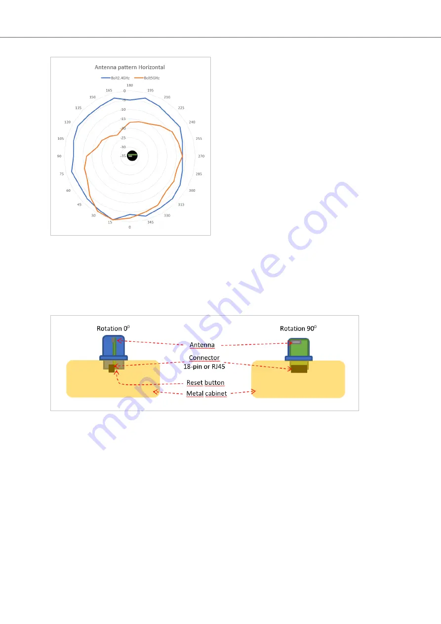
Figure 42. Antenna pattern Horizontal
Vertical Views
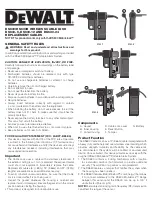
These diagrams show the antenna pattern when looking at the Bolt from the side in two different rotations, 0°
and 90°.
The Bolt is mounted in a metal cabinet illustrated by the yellow box below the Bolt.
Figure 43. Antenna pattern, Boltrotation 0° and 90°
Diagram Analysis
The vertical antenna gain is fairly omnidirectional for both frequencies.
It is also clear to see that the metal cabinet where the Bolt is mounted will increase the gain “upwards” in
reference to the surface where the Bolt is mounted. Thus the gain “downwards” is limited as expected.
Radio Antenna Patterns
Anybus
®
Wireless Bolt Serial
™
SCM-1202-143 2.0
Page 57 of 60


