


62
C23UE004-2109
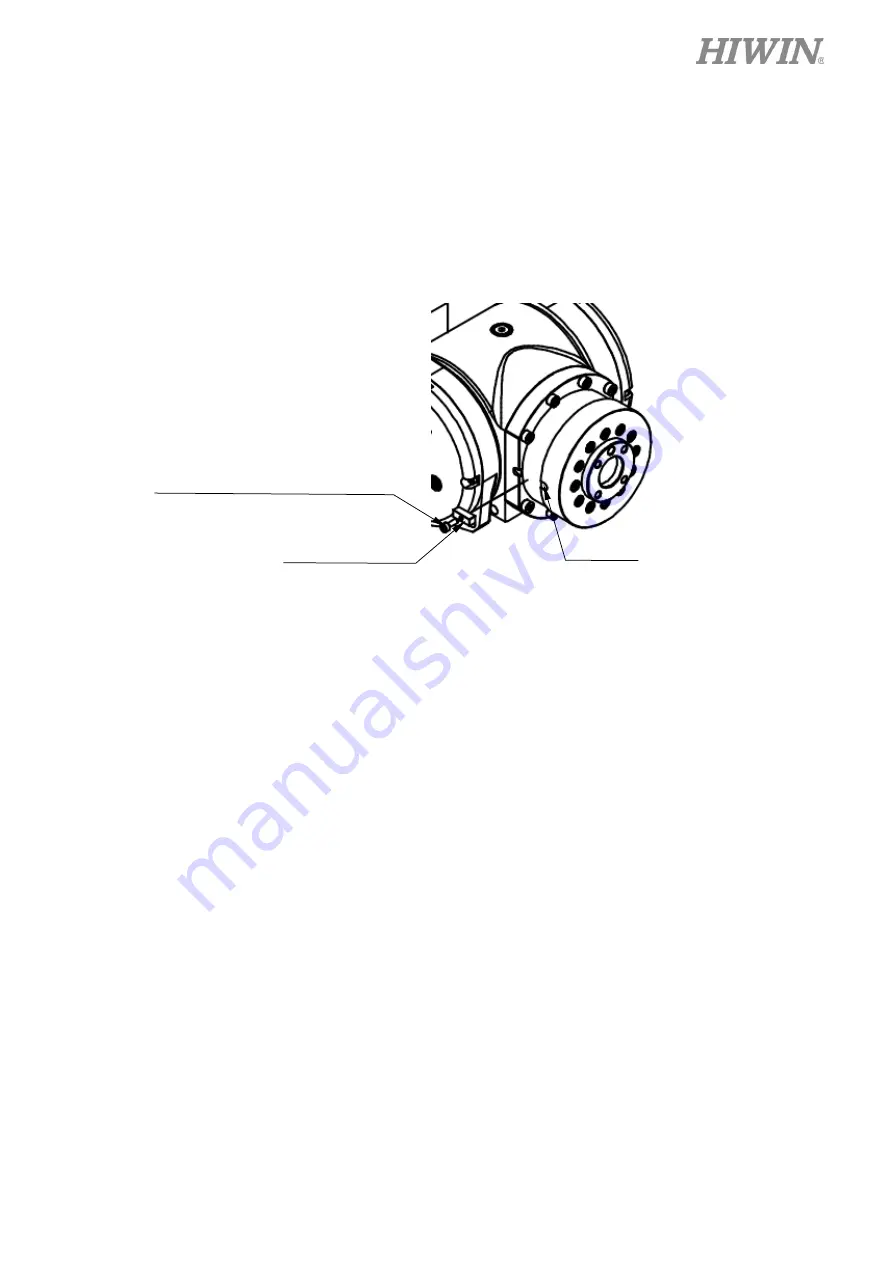
J6-axis Zero-position setting (please refer to the Figure 4-7)
Step1.
Operate J6 at low speed to align the calibration mark with the keyway.
Step2.
Insert the calibration tool(B) to the keyway to calibrate Zero-position. (The hexagon
socket screw can be secured to the calibration tool(B) in advance.)
Step3.
Finish calibration and remove the calibration tool(B) by using the hexagon socket screw.
Step4.
Clear encoder by HRSS.
Step5.
Zero-position setting of J6 axis is completed.
Figure 4-7 Illustration of J6-axis Zero- position setting
Clear encoder by HRSS (Refer to HRSS Software Manual)
Step1.
Select the “JOINT” as the coordinate system.
Step2.
Move the robot to the Zero-position.
Step3.
Click Main Menu>>Start-up>>Master>>Zero Position.
Step4.
Double click the axis to clear encoder. (As shown in Figure 4-8)
Calibration tool(B)
Keyway
Hexagon socket head cap screw
M3
×
0.5P
×
8L(Nylok)
Содержание RA610-GC
Страница 1: ...www hiwin tw User Manual Articulated Robot RA610 GC Original Instruction ...
Страница 42: ...40 C23UE004 2109 Figure 2 3 b RA610 1355 GC Outer dimension and motion range ...
Страница 43: ...41 C23UE004 2109 Figure 2 3 c RA610 1476 GC Outer dimension and motion range ...
Страница 44: ...42 C23UE004 2109 Figure 2 3 d RA610 1672 GC Outer dimension and motion range ...
Страница 45: ...43 C23UE004 2109 Figure 2 3 e RA610 1869 GC Outer dimension and motion range ...
Страница 47: ...45 C23UE004 2109 Figure 2 4 b RA610 1476 GC Wrist moment diagram ...
Страница 48: ...46 C23UE004 2109 Figure 2 4 c RA610 1672 GC Wrist moment diagram ...
Страница 49: ...47 C23UE004 2109 Figure 2 4 d RA610 1869 GC Wrist moment diagram ...
Страница 50: ...48 C23UE004 2109 Figure 2 4 e RA610 1151 GC Wrist moment diagram mm mm ...
Страница 65: ...63 C23UE004 2109 Figure 4 8 Clear encoder by HRSS ...
Страница 73: ...71 C23UE004 2109 Table 6 3 Inspection schedule ...


