


BSW
FAN-COIL HIGH PRESSURE
18
06.18 Ref. 207483 Rev.102
HYDRAULIC CONNECTION
MAIN HYDRAULIC CONNECTION
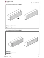
CAUTION! Always use a wrench and counter-wrench for connection of the
coil to the pipes (pic. 25). If the valve is installed, suitably insulate the valve
body with insulating material (pic. 26).
Connect the water inlet and outlet pipes, observing the indications given on the
side of the unit. Correctly insulate the water supply pipes to prevent dripping
during the cooling mode of operation. A shutoff valve should be inserted on the
water supply pipe and a balancing valve on the outlet pipe. The valve body and
balancing valve should also be properly insulated to prevent dripping. It is the
installer’s responsibility to insulate properly and the manufacturer cannot be held
liable for any insulation work.
NOTE: It is always advisable to install the valve. In the heating mode of
operation the valve reduces consumption because upon reaching the set
temperature the circulation of water is stopped to avoid wasting energy
(the fan coil would otherwise continue to heat like a radiator, even with the
motor at a standstill). In the cooling mode of operation the valve stops the
circulation of water when the set temperature is reached, this stopping the
internal exchanger from continuing to condense water with possible
undesirable dripping onto the floor. It also reduces chiller operation with
consequent energy saving.
CONDENSATE WATER DRAINAGE
The condensate drain pipe should slope downwards by at least 3 cm/m and
should not have ascending or throttled sections in order to ensure a regular flow
of water. It is advisable for a trap to be fitted. The condensate drain pipe should
be connected to a rainwater drainage system. Do not use sewage systems to
avoid possible rising of smells in the event of evaporation of the water in the
trap. Upon completion of work, check that the condensate flows out properly by
pouring water into the tray. The condensate water drainage system should be
fabricated in a workmanlike manner and should be periodically checked.
The manufacturer cannot be held liable for any damage caused by dripping in
the absence of a valve or of periodic maintenance of the drainage system.
ELECTRICAL CONNECTIONS
RECOMMENDATIONS!
Before carrying out electrical connections, ensure that the electricity supply to
the supply line has been cut off, checking that the on-off switch is in the OFF
position.
- Only qualified electricians should carry out the electrical connections.
- Check that the mains supply is single-phase 230 Vac/1/50 Hz (± 10%).
- Operating the unit with voltages outside the above limits could cause malfun-
ction and renders the warranty null and void.
- The power supply line should be fitted with at least a switch isolator in confor-
mity with European standard EN60947-3.
- Make sure that the electrical system is suitable for providing not only the wor-
king current required by the unit, but also the necessary current for powering
household and other electrical appliances already in use. Any electrical and
mechanical alterations or tampering render the warranty null and void.
The cables should be sufficiently long so that they are not permanently taut or
create throttling or compression on metal parts.
The power cables should be sufficiently long so that in the event of accidental
tugging the active wires are subjected to stress before the earth wire. Connect
the earth wire to the relative terminal marked with the symbol
. Comply with
the safety regulations in force in the country of installation.
CONNECTIONS TO THE TERMINAL BOARD
The electrical connections should be made to the terminal boards on the side of
the appliance. Each terminal is identified by the label to be found on the terminal
boards.
CAUTION! FAILURE TO COMPLY WITH THE INDICATED CONNECTIONS
MAY CAUSE MOTOR BURNOUT!
Pic. 26
Pic. 25
Содержание BSW 1
Страница 2: ...BSW FAN COIL HIGH PRESSURE 2 06 18 Ref 207483 Rev 102 ...
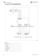
Страница 19: ...BSW FAN COIL HIGH PRESSURE 06 18 Ref 207483 Rev 102 19 WIRING DIAGRAM MOD 1 3 ...
Страница 20: ...BSW FAN COIL HIGH PRESSURE 20 06 18 Ref 207483 Rev 102 WIRING DIAGRAM MOD 4 5 ...
Страница 21: ...BSW FAN COIL HIGH PRESSURE 06 18 Ref 207483 Rev 102 21 WIRING DIAGRAM MOD 6 7 ...
Страница 24: ...BSW FAN COIL HIGH PRESSURE 24 06 18 Ref 207483 Rev 102 NOTES ...