8
9
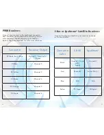
PWM Receivers
Connect your receiver to the numbered connector.
The connectors are marked and should plug into the
corresponding channel output on your receiver.
Refer to the following chart for color cross reference.
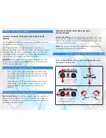
S-Bus or Spektrum
®
Satellite Receivers
Connect the plugs marked S to your receiver as shown
in the chart below.
Connector
Receiver Output
#1 Black, Red, White
Ground(-), Power out(+)
Signal
#2 Blue
Channel 2
#3 Yellow
Channel 3
#4 Green
Channel 4
#5 Orange
Channel 5
#6 Purple
Channel 6
Connector
Color
S BUS
Spektrum
®
Black
Ground(-), Power
out(+)
Signal
Ground (-)
Red
Channel 2
Power Out (+)
Blue
N/A
N/A
Yellow
TX Signal
TX Signal


