


--- 17 ---
Fig. 20
(Brown)
(Cord)
(Cord)
(Blue)
(Carbon brush)
(Stator)
(Noise suppressor)
Red
Y
ellow
Brown
(Cord)
(Cord)
Blue
(Carbon brush)
(Stator)
Brown
Brown
Blue
Red
Brown
Red
(Noise suppressor)
(Stator)
(Stator)
Fig. 21
Fig. 22
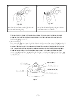
(6) Wiring of switch
General internal wiring can be accomplished by referring to step (7). The following are special instructions for
switch connection.
(a) Disconnection of reversing switch wiring
As illustrated in Fig. 20, insert a small flat-blade
screwdriver into the slots near the terminals and pull out
the lead wires.
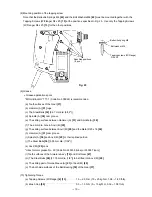
(b) Disconnection of variable-speed control switch wiring
As illustrated in Fig. 22, insert a small flat-blade
screwdriver into the slots near the terminals and pull out
the lead wires in the same manner as illustrated in
Fig. 20.
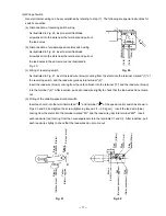
(c) Wiring of reversing switch
As illustrated in Fig. 21, insert the lead wire (brown) coming from the stator into the terminal marked "(1)" of
the reversing switch, and the lead wire (yellow) into terminal "(2)".
Insert the lead wire (brown) coming from the carbon brush into the terminal "(3)" and the lead wire (brown)
into the terminal "(4)". After insertion, pull each lead wire slightly to check that the lead wires do not come
out.
(d) Wiring of the variable-speed control switch
Insert each cord into the terminal marked "1 " and terminal "2 " of the speed control switch as shown in
Figs. 20 and 22, and tighten the screw (tightening torque: 2.5 --- 3.0 kg
•
cm). Insert the lead wire (blue)
coming from the stator into the terminal marked "M1" and the lead wire (red) into terminal "M2". Insert
each lead wire (red) coming from the noise suppressor into the terminals C1 and C2. After insertion, pull
each lead wire slightly to check that the lead wires do not come out.
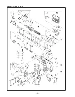
Содержание WF 4V
Страница 25: ... 22 Assembly Diagram for WF 4V ...


