


--- 8 ---
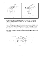
(3) Setting for collated screws
Ensure that the first one of the collated screws is set to the
screw mark on the slider. If the screws are set otherwise
than indicated in Fig. 8, the plasterboard surface may be
scratched by the bit (because of insufficient feed of the
screw series) or screws may be wasted (because of
excessive feed of the screw series).
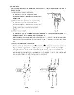
(4) Plasterboard powder deposited on the slider surface and on the roller on top of the slider as shown in Fig. 9
may result in improper operation. Ensure that these parts are frequently cleaned with compressed air before
the slider movement becomes slow.
Likewise, plasterboard powder deposited on the mounting ends of the collated screw attachment may make
removing and mounting difficulty. Ensure these parts
are cleaned frequently. (In particular, the powder tends
to easily stick when working with the screwdriver held
upward.)
(5) The small hole on either side of the handle section is important for ventilating gases. Ensure that this hole is
not blocked.
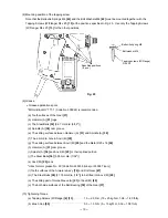
(6) Reference for tightening depth
This screwdriver is designed to adjust the tightening depth by turning the Knob. Ensure that the tightening
depth is adjusted following the procedure given below so that the screws are properly tightened without such
errors as the screw head remaining above the plasterboard surface or sunk below it after tightening.
(a) Screws (L) 25 mm (1") --- 32 mm (1-1/4") [using top adjuster No.1 (small)]
(b) Screws (L) 35 mm (1-3/8") --- 41 mm (1-5/8") [using top adjuster No. 2 (large)]
Screw mark
Fig. 8
Slider
Roller
Slider case
Fig. 9
Counterclockwise
Clockwise
Set the stopper at "25 - 32".
Knob
Fig. 10-1
Set the stopper at "35 - 41".
Fig. 10-2
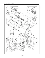
Содержание WF 4V
Страница 25: ... 22 Assembly Diagram for WF 4V ...


