6 - 3
6-1-4 Setting test equipment
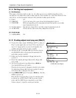
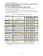
(1) Oscilloscope
The names of switches, knobs, modes, etc. of oscilloscope may vary slightly depending on the
manufacturer or model. Since some oscilloscopes may have switches, etc. other than the above that
must be set, see the instruction manual of the particular oscilloscope for details.
1) Probe:
10:1
2) TIME/DIV:
10 or 20 µs (except for a case where some designation is given)
3) VOLTS/DIV:
Will vary depending on the measurement object (except for a case where
some designation is given)
4) Synchronization:
Internal sync (except for a case where some designation is given)
5) AC/DC/GND:
AC (except for a case where some designation is given)
(2) Vectorscope
1) SATURATION:
75%
6-1-5 Starting adjustment program (ZMAP)
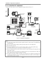
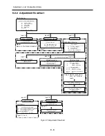
1) Connect the video camera, DSP-R jig and PC as shown in
Fig. 2-1, and supply power to them. If the connection of
jig, etc. is inappropriate or power is not supplied, the
adjustment program will not start normally.
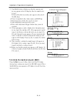
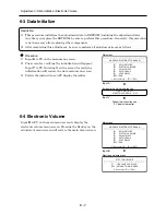
2) Operate the PC to start MS-DOS. For details on how to
start MS-DOS, refer to the instruction manual of PC,
since this varies for each PC.
3) Make sure that the adjustment floppy disk is write-
protected.
4) Insert the adjustment floppy disk into the floppy disk
drive of PC.
5) Use the PC keyboard to type
A:
and press
Enter
key.
(See the MS-DOS screen-1 and 2)
The letter to be input is to designate the drive into which
the adjustment floppy disk has been inserted. If using a
drive other than A, designate the drive.
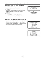
6) Input
ZMAP_2002
(space)
1
and press
Enter
key. (See the
ZMAP input screen)
The number to be input after a space is to designate the
serial port no. of PC. If the PC has two or more serial
ports, and the DSP-R jig is connected to a port other
than serial port 1, input the serial port number.
MS-DOS screen-2
ZMAP input screen
C>
C>A:
A>ZMAP_2002 1
C>A:
A>
MS-DOS screen-1
Press Enter key.
Input ZMAP_
2002 (space) 1.
Adjustment > Preparations for Adjustment
Input A and press
Enter key.
(Continued on next page)

