5 - 1
Disassembly and Reassembly
5
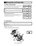
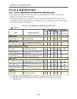
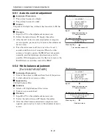
Fig. 5-1-1 Disassembly Flowchart
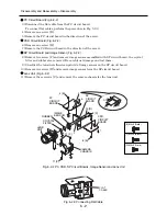
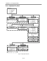
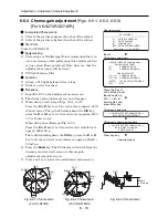
Fig. 5-2-1 Chassis L and R
5-1 Order of Disassembly
Refer to “Disassembly Flowchart” in Fig. 5-1-1 for the order of
removing components. When reassembling components, use the
reverse order to removal unless otherwise specified.
Note:
When replacing components in the VK-S274R/S274ER/K274R/
K274ER, be sure to use only those shown in "Replacement Parts
List".
Reading Disassembly Flowchart:
After locating the target component in the flowchart, remove all
components of the target in sequence, following the arrows
(routes) from the top of flowchart.
5-2 Disassembly
Information:
Numbers in figures are step numbers in disassemble procedure, and letters in brackets [ ] show
the types of screw.
Chassis L and R (Fig. 5-2-1)
1) Remove four screws [A] and remove the chassis L.
2) Remove two screws [A] and remove the chassis R.
Component name
Chassis R
Chassis L
PC Circuit Board
Item
No.
1) and 2)
3) to 5)
CSR Circuit Board
6) and 7)
8) and 10)
SP Circuit Board
Image Sensor
Lens unit
11)
SP
CIRCUIT
BOARD
CSR
CIRCUIT
BOARD
PC
CIRCUIT
BOARD
B
A
CHASSIS L
A
B
LENS
UNIT
CHASSIS R
1 [A]
1 [A]
2 [A]
[A] M2×3 (Black)

