background image

Page 15 of 32 


BASIC OPERATION


Turning On the Monitor


1.    If the Camera Cable VC-90A is not installed, please connect it to the VF CABLE connector on  the 

rear of the viewfinder.  Secure the cable with the supplied cable fixing clamp. 


2.    Power ON the monitor by pressing the 

POWER 

button on the front lower right for 2 seconds or 

more. 

The monitor has a stand-by or power save mode.   When in standby mode, the display is off but 

the electronics inside the VF are on.  In order to turn monitor on, press the 

POWER 

button. 


3.    The camera video is automatically displayed.  Assure that the camera is outputting video and that 

the VF is not in “STILL IMAGE” mode (refer to page 20). 


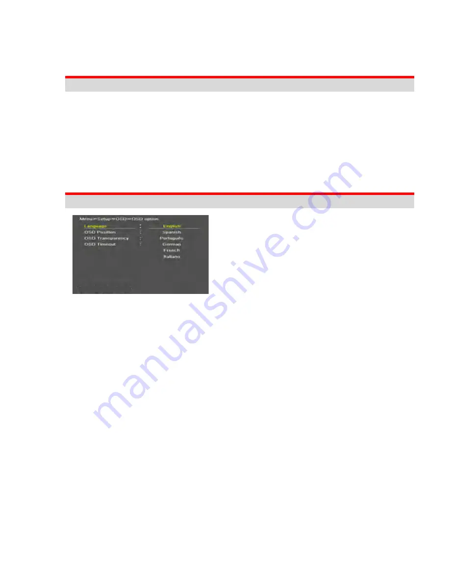
On Screen Menu Language Selection


SETUP -> OSD -> OSD Option -> Language 


The  menu  can  be  shown  on  the  screen  in  the 

selected language. 


Supported 

Language: 

English, 

Spanish, 

Portuguese, German, French, Italian 

Содержание VF-PBM307

Страница 1: ...HD COLOR VIEWFINDER VF PBM307 OPERATING INSTRUCTIONS Please read these operating instructions carefully for proper operation and keep them for future reference ...

Страница 2: ...Page 2 of 32 This page left intentionally blank ...

Страница 3: ...10 Typical Menu Operation 11 COMPOSITION 11 CAMERA MOUNTING PROCEDURES 12 VIEWFINDER ADAPTORS FOR HITACHI HDTV CAMERAS 12 BASIC OPERATION 13 TURNING ON THE MONITOR 13 ON SCREEN MENU LANGUAGE SELECTION 13 ON SCREEN MENU SELECTION AND ADJUSTMENT 14 HOW TO ADJUST THE OSD SCREEN 14 PICTURE MENU OPTIONS 15 VIDEO MENU OF EACH INPUT MODE 15 ADJUST 15 COLOR TEMPERATURE CONTROL 15 SCAN 15 ASPECT RATIO 16 Z...

Страница 4: ...2 I P MODE 22 DITHERING 22 INTERNAL PATTERN 22 NR NOISE REDUCTION 23 OSD ON SCREEN DISPLAY 23 OSD OPTION 23 UNDER MONITOR DISPLAY COLOR TALLY R G MODE ACTION 23 INFORMATION 24 ON SCREEN DISPLAY MENU SYSTEM 25 MENU TREE ORGANIZATION 25 VIDEO 26 MARKER 27 SETUP 28 OSD 29 INFORMATION 29 SUPPORTED INPUT MODES 30 SUPPORTED SIGNALS 30 EXTERIOR DIMENSIONS 30 WARRANTY SUPPORT 31 STANDARD PRODUCT WARRANTY ...

Страница 5: ... your safety in mind However improper use can result in potential electrical shock or fire hazards To avoid defeating the safeguards that have been built into this new product please read and observe the following safety points when installing and using this new product and save them for future reference Please read Instructions 1 Follow Instructions All operating and use instructions should be fo...

Страница 6: ...ourself as opening or removing covers may expose you to dangerous voltages or other hazards Refer all servicing to qualified service personnel 12 Safety Check Upon completion of any service or repairs to this product ask the service technician to perform safety checks to determine that the product is in proper operating condition and the front seal is intact 13 Mounting The product should be mount...

Страница 7: ...ono Color display modes Preset Gamma selection User selectable gamma curves OSD Graphic based On Screen Display 6 Languages UNICODE System Markers Preset and user programmable Safety Zone 16 9 4 3 aspect ratio EBU action graphics preset safety zones Crosshair center marker Selectable color for Safety Marker and Crosshair markers Auto Calibration K 10 Klein UMD Programmable characters for indicatin...

Страница 8: ...es values of the function selected on the main OSD menu Executes function by OSD help commands in main OSD menu ENTER Activates OSD menu of input source Executes functions by OSD help commands in main OSD menu F1 Executes functions of user programmed item Undefined Aspect Mono Blue only Marker size Safety Marker Still image Zoom Gamma select I P Mode Marker Preset 1 2 Max Brightness F2 POWER Power...

Страница 9: ...PIN N A 4 PIN N A 14 PIN R Tally ON 3 3v OFF 0V 5 PIN Pr Video 15 PIN G Tally ON 3 3v OFF 0V 6 PIN N A 16 PIN N A 7 PIN N A 17 PIN N A 8 PIN N A 18 PIN GND 9 PIN GND 19 PIN 12VDC IN 10 PIN N A 20 PIN GND Rear Panel Talent Tally LED Camera Cable support clamp Camera to Viewfinder Connector 20pin ...

Страница 10: ...ided Most menus consist of three levels to set up the options but some require greater depth for the variety of settings If you press the MENU button only the first and second level of the menu system will appear on the monitor screen The third level can be displayed by pressing ENTER If a menu has more than three levels the pop up dialogue box will be displayed as the fourth or fifth level To dis...

Страница 11: ... the second menu option 5 Press ENTER to move to the third level Some menu options require additional steps 6 Press MENU to return to the previous menu to return to monitor viewing Composition 1 1 each VF PBM 307 LCD Color viewfinder 7 inch 16 9 2 1 each VF HO307 Viewfinder screw on hood with rubber protective edging 3 1 each VC J90A 20 pin Viewfinder to camera chassis shielded cable 4 1 each Oper...

Страница 12: ...0 SK HD1000 Z HD5000 Z HD6000 Note that the VF mount is installed on the CA HF1500 CA HF1300 CA HF1200 CA HF1000 CA HD1000 or CX HD1300 cable adapter chassis If you are using the AT 90 or AT 500 please install the chassis support bracket with the 4 supplied screws part 8BDF000567 PAN HD M4X8 Fe Ni Screw the bracket to the bottom of the VF PBM307 as depicted on the left NOTE Your VF PBM307 may alre...

Страница 13: ...secure it in place Assure that the viewfinder is mechanically fixed to the support bracket and that it does not wobble or fall Mount the viewfinder and bracket assembly on the cable adapter by first turning the Gray Lock ring second by depressing the lock lever as shown on the right To remove hold on to the viewfinder and perform the above steps again while pulling the viewfinder away from the cam...

Страница 14: ...ock handle Plug in the supplied VC J90A 20 pin Viewfinder to camera cable by gently rotating it until it seats in the receptacle Tug on the connector to make sure it is locked and firmly seated OPTIONAL So that the VC J90A 20 pin Viewfinder cable does not get lost we recommend that it be mechanically affixed to the rear of the viewfinder with the provided clamp Note that the clamp should not be ov...

Страница 15: ...ore The monitor has a stand by or power save mode When in standby mode the display is off but the electronics inside the VF are on In order to turn monitor on press the POWER button 3 The camera video is automatically displayed Assure that the camera is outputting video and that the VF is not in STILL IMAGE mode refer to page 20 On Screen Menu Language Selection SETUP OSD OSD Option Language The m...

Страница 16: ... the OSD screen 1 Press the MENU button and then UP DOWN button to select each menu 2 Press the ENTER button and then use UP DOWN ENTER MENU button to display the available menu Your monitor s OSD On Screen Display may differ slightly from what is shown in this manual ...

Страница 17: ...or Setting the Color temperature or adjusting RGB gain value directly User User setting RGB gain value VAR 3200o K 11000o K Often used value 11000o K 9300o K 6500o K 5400o K 3200o K SCAN Over Scan 95 input size and fit the selected display size Zero Scan 100 Input size and fit the selected display size Pixel to Pixel Display size is an input size If input resolution is higher than the panel s 800h...

Страница 18: ...is depressed NOTE When operating the VF in 4 3 aspect ratio also select 4 3 aspect on the camera VF Menu to avoid geometric distortion to the displayed image Zoom Magnifies the picture by 2X 3X 4X 5X ratios The YELLOW box marker indicates the zoom ratio selected above Press Adjust knob or Enter button to see the enlarged picture selected above Turn the Adjust knob to move the zoom zone within the ...

Страница 19: ...zone divisions Mono Blue Only Mono Color Displays a monochrome B W or Color image Blue Only Picture is displayed in blue color only For verification of proper color display with SMPTE color bars generated by the HITACHI cameras Max Brightness Max Brightness On Off For observing a dim object or testing the device s back lamp ...

Страница 20: ...panel size 2 3x User Marker User programmable marker size adjustment using the X1 2 3 and Y1 2 3 row column settings Example of 16 9 preset marker Yellow User marker white Example of 4 3 preset marker Yellow User marker white Safety Area Preset Safety Area For selection of one of the following safety zone markers 16 9 95 93 90 88 80 4 3 95 93 90 88 80 EBU Action 16 9 14 9 4 3 EBU Graphic 16 9 14 9...

Страница 21: ...arker line thickness setting 0 10 0 thin lilne 10 thick line Marker Color Crosshair Marker Line Color Select Marker line color White Yellow Blue RED Black Safety Zone Line Color Select the Safety zone line color White Yellow Blue RED Black Preset 1 Preset 2 Marker preset memories ...

Страница 22: ...tton Description Undefined No Assignment Aspect Sets the aspect ratio of the images Mono Blue Only Execute Mono color or Blue Only Marker size Marker size Select Safety Marker size Safety size Select Still image Toggles picture status between motion and still image Zoom Zoom function is operated Off 2x 3x 4x 5x Gamma Select Select Gamma curve I P Mode Line Doubler Inter Field Field Merge function ...

Страница 23: ...screen saver functions to avoid panel burning BG Background Gray Selects the gray background level of the monitor for images that do not fill the entire screen Power save Mode Power Save Mode on off Set ID Active Set ID For remote control must set unique ID number for each unit 01 99 ...

Страница 24: ...ght Adjust Inverter dimming Level select 0 100 Gamma Select Gamma Level Select 0 8 high λ 3 0 low λ I P Mode Line Doubler Inter Field Field Merge function on off Dithering Dithering 1 bit 2 bit 3 bit off function on off Internal Pattern 100 Color Bars 75 Color Bars Luma RGB White Black RED Blue Green NR Noise Reduction Noise Reduction on off NR is for Video signal HD SDI Composite S Video Y Pb Pr ...

Страница 25: ...isable blending OSD background with video image OSD Timeout OSD gone time setting 3 200 Under Monitor Display color Tally R G mode action Channel 12 Channel 12 Tally Red UMD UMD display on off UMD Character UMD Character Select UMD Position UMD display position select L T C T R T L B C B R B Tally Green UMD FG Color UMD Character color Select RGB_255_192_128_Transparent UMD BG Color UMD BG color S...

Страница 26: ...yle Select Input Format Custom Label Input Label Can be used to program the Camera ID number or the cameraperson s name so that it is superimposed on the display Information Version Release day Release time operating time FPGA Version and Calibration ID ...

Страница 27: ...Page 27 of 32 ON SCREEN DISPLAY MENU SYSTEM Menu Tree Organization ...

Страница 28: ...Page 28 of 32 Video ...

Страница 29: ...Page 29 of 32 Marker ...

Страница 30: ...Page 30 of 32 Setup ...

Страница 31: ...Page 31 of 32 OSD Information ...

Страница 32: ...play Panel 7 LCD Resolution 1024 horizontal by 600 vertical Contrast 900 1 Brightness 400 cd m2 Viewing Angle R L 165 Typ U D 165 Typ Supported Signals Component YPbPr RGB 1080p 1080i 720P 480i 576i 480P 576P Analog Input Level 1 0Vpp Y With sync 0 7Vpp Pb Pr Exterior Dimensions VF PBM 307 ...

Страница 33: ...must be returned properly packed to an authorized Hitachi Kokusai Service Station Any damage caused by failure to observe proper packing or to observe instructions for installation operation and maintenance as contained in the Instruction Manual furnished with each unit by accident in transit or elsewhere will not be covered by the Warranty Shipment to authorized Hitachi Kokusai Service Stations m...

Страница 34: ...Page 34 of 32 ...

Отзывы: