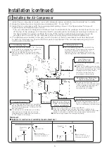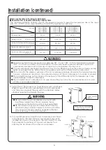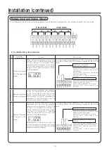
5. Install the Air Compressor on Level Ground with a Sufficient
Weight Load. If there is a gap between the air compressor
and the ground, adjust the gap with the attached rubber
vibration isolators to eliminate the gap.
6. For parallel operation, install the air compressors as shown
in the figure to the right. If the air compressors cannot be
installed as shown in the figure to the right, install in a way
that prevents the exhaust of one air compressor from
entering the air intake of the other air compressor.
Installation(continued)
6
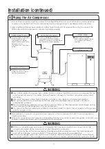
● Keep the ambient room temperature in between 32° F and 104° F. If the temperature exceeds
104° F or there is a defect in the installation, the air compressor protective devices may stop air
compressor operation and/or damage or reduction in compressor life may occur.
● The air compressor discharges air exhaust from the top. Make sure that there are no items such as
lights, or wirings that are above the air compressor and can be affected by the exhaust air.
● Do not modify the intake or exhaust of the air compressor package, otherwise the temperature may
become unbalanced, resulting in the protective devices of the air compressor to function improperly.
● Do not install ducting on the intake or the exhaust of the Oilfree Scroll Air Compressor, as it may
cause damage to the air compressor.
● Do not install the air compressor in an area above the ground, as the air compressor and/or parts
of the air compressor may fall.
WARNING
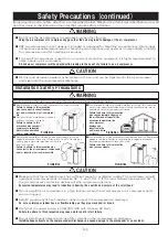
● Do not install the air compressor on ground with
insufficient weight load. Do not operate the air
compressor attached to a pallet or packaging table.
● Do not install on any type of rubber other than the
attached rubber vibration isolators and do not bolt to
the concrete. This may result in excessive vibration
and/or damage to the air compressor.
WARNING
SRL-7.5M6LL
SRL-7.5M6ML
SRL-7.5M6LH
SRL-7.5M6MH
SRL-11M6LL
SRL-11M6ML
SRL-11M6LH
SRL-11M6MH
SRL-16.5M6LL
SRL-16.5M6ML
SRL-16.5M6LH
SRL-16.5M6MH
Generate Heat kJ/h
25,116
36,000
54,000
Cooling Air Flow CFM (
㎥
/min)
990 (28)
1,240 (35)
1,520 (43)
Cooling Air Differential Temperature
° F (℃ )
63 (35)
63 (35)
63 (35)
Required ventilating capacity (1)
CFM (
㎥
/min)
2,472 (70)
3,532 (100)
5,297 (150)
Required ventilating capacity (2)
CFM (
㎥
/min)
777 (22)
1,130 (32)
1,695 (48)
【Please see the table to the below for Reference】
■ Generated Heat & Required Ventilating Capacity Table
The required ventilating capacity value is the required capacity to keep the temperature rise in the room
within 9° F (5℃ ) when only one Oilfree Scroll Air Compressor is operating.
Item
Model
Install the Air Compressor
on Level Ground with a
Sufficient Weight Load.
Rubber vibration
isolators
Exhaust air
Exhaust air
Intake air
Intake air
39 in. or more
Содержание SRL Series
Страница 38: ...Wiring Diagram 34 SRL 7 5M6LL ML LH MH SRL 11M6LL ML LH MH ...
Страница 39: ...Wiring Diagram continued 35 SRL 16 5M6LL ML LH MH ...
Страница 42: ...Log Book 38 ...
Страница 43: ...Log Book 39 ...


