background image

CHAPTER5  OPERATING

18

In the request message the first two bytes are used for parameter identification. The first digit (7) denotes the
function “Change parameter value (array word)” (refer to chapter 3.2). The second digit along with the second
byte (3 and 93) indicates parameter number 916. Byte 3 (01) denotes sub-index in the array parameter, in this
case “01” means the first index in the array. Bytes 7 and 8 (00 3D = 61dec) contains the parameter number that
shall be mapped. This means that in the PZD3 place the read value of parameter A038 (Profibus parameter
number 61dec) shall be transferred from the inverter to the master every bus-cycle.
In the response message, the first digit (4) indicates the function “Transfer parameter value (array word)”. Sub-
index (01 00), value (00 3D in bytes 7 and 8) and parameter number (x3 94) are mirrored from the request. In the
PZD3 field (word 7) the value (01 F4 = 500dec, 5.00 Hz) of “Jogging frequency” is transferred.

5.4.3 Writing a two byte array parameter #2

In this third example, we are configuring PZD3 to contain the value of parameter A004, “1

st

 Maximum frequency”

in the request 

from the master to the inverter

. PPO2 is used. On Profibus parameter A004 corresponds to

parameter number 62 (3Eh). This is configured with parameter number 915 (393h), “Assignment of PZD write
word” (see also chapter 5.3.3 and 5.5).

PKW

PZD

Word

1

PKE

2

IND

3

PWE

4

PWE

5

STW
ZSW

6

HSW

HIW

7

PZD3

8

PZD4

9

PZD5

10

PZD6

Request:

PLC->Inverter

73 93

01 00

00 00

00 3E

04 7F

20 00

00 4B

00 00

00 00

00 00

Response:

Inverter->PLC

43 93

01 00

00 00

00 3E

03 37

20 00

01 F4

00 00

00 00

00 00

In the request message the first two bytes are used for parameter identification. The first digit (7) denotes the
function “Change parameter value (array word)” (refer to chapter 3.2). The second digit along with the second
byte (3 and 93) indicates parameter number 915. Byte 3 (01) denotes sub-index in the array parameter, in this
case “01” means the first index in the array. Bytes 7 and 8 (00 3E = 62dec) contains the parameter number that
shall be mapped. In the PZD3 field (word 7) the value (00 4B = 75, 75 Hz) of  “1

st

 Maximum frequency” is

transferred. That is, parameter A004 will be written with the value 75.
In the response message, the first digit (4) indicates the function “Transfer parameter value (array word)”. Sub-
index (01 00), value (00 3E in bytes 7 and 8) and parameter number (x3 93) are mirrored from the request. As
can be seen in word 7 (PZD3) 01 F4h is transferred from the inverter to the master, that is the mapping from the
example above (5.4.2) is still present.

*To start the inverter the Profibus state machine must be shifted in a correct way. This may be done in two steps.
First the control word should be set to 04 06 (Enter 

Ready to switch-on state

) and then to 04 7F (Enter 

Operating

state

). Refer to the state diagram in Figure 5-2.

Содержание SJ-PB

Страница 1: ...handy for future reference Make sure to reach this manual to the end user Table of Contents Chapter1 INTRODUCTION 1 Chapter2 INSTALLATION 5 Chapter3 WIRING CONNECTING 6 Chapter4 SETTING 8 Chapter5 OPERATING 10 Chapter6 COUNTERMASURE FOR ABNORMALIT 21 Appendix PARAMETER CROSS REFERENCE LIST 22 SJ300 L300P SERIES SJ PB T Profibus DP Option Profibus DP Option Profibus DP Option Profibus DP Option NB6...

Страница 2: ...l 1 Please consent that mentioned items of this manual may be change without permission 2 Keep this manual carefully not to lose because it can not be reissued 3 All right reserved 4 Contents in this manual is written to make assurance doubly sure but but please contact if you have some doubts about spelling mistakes omitted word etc 5 Please agree that there is no responsibility for effects resul...

Страница 3: ...minor to moderate injury or serous damage to the product The situation described in may if not avoided lead to serious results Important safety measures are described in CAUTION as well as WARNING so be sure observe them Notes are described in this manual in Note Carefully read the contents and follow them exactly CAUTION In all the illustrations in this manual covers and safely device are occasio...

Страница 4: ...k Make sure that only qualified persons will perform maintenance inspection and part replacement Before starting the work remove metallic objects from your person wristwatch bracelet etc Be sure to use tools protected with insulation Otherwise there is a danger of electric shock and or injury Note Never modify the unit Otherwise there is a danger of electric shock and or injury CAUTION Installatio...

Страница 5: ... number 3 Date of purchasing 4 Contents of inquiry Damage parts and its condition etc Question parts and their contents etc In order to shorten impossible working time standing spare unit is recommended 1 2 2 WARRANTY OF THE PRODUCT This product is guaranteed to last for one year after purchase But the next case is toll repair even if within warranty period 1 In case caused by operating mistake an...

Страница 6: ...y supports the services relevant to speed control applications In a control system the option board will act as a slave that can be read and written to from a Profibus DP master It will not initiate communication to other nodes it will only respond to incoming telegrams Note RS485 communication function is disabled by installing SJ PB T to the inverter Difference between SJ PB and SJ PBT is only c...

Страница 7: ...imum number of nodes 126 Maximum number of I O 244 bytes slave Bus topology Master Slave communication The figure below gives an overview of a Profibus DP network Cyclic user data transfer between DP Master and DP Slaves Watch Dog Timer at the DP Slaves Connecting or disconnecting stations without affecting other stations Powerful diagnosis mechanisms 3 hierarchical levels of the diagnosis message...

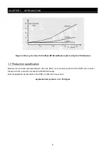
Страница 8: ... PB T is in accordance with SJ300 L300P series inverter Please refer the instruction manual of SJ300 L300P series But only application temperature of SJ PB T is different Please note application temperature 0 to 50 degree Figure 1 4 Bus cycle time of a Profibus DP Mono Master system 2 bytes I O data slave ...

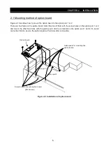
Страница 9: ...them with the screw holes on the option port 1 or 2 and mount the other two holes with the guide posts which are located on the option port 1 and 2 To avoid connection failure secure the option board with screws after connection Option board Guide posts for mounting the option board Option port 1 Option port 2 Screw holes for secure option board M3 Screws Figure 2 1 Installation of option board ...

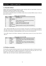
Страница 10: ...ers RS485 to fibre optics might require external power supply from these pins RTS is used in some equipment to determine the direction of transmission In standard applications only A Line B Line and Shield are used The SJ PBT connects to the Profibus network with a 6 poles 2pieces connector For the pin layout refer to Table 3 2 Table 3 2 Pin Layout of SJ PBT Pin Name Function 1 B Line in Positive ...

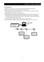
Страница 11: ... stop measures are taken to stop the inverter in the event of a network fault a Remove the Power supply of the Inverter when the network master detects a communication fault b When the master detects a communication fault turn on the intelligent input terminal which would be allocated FRS RS and or EXT function 6 Basic components for construction of Profibus DP application are shown bellow Refer t...

Страница 12: ...not be changed during operation the module needs to be re powered in order for the change to have effect 4 1 2 Baudrate The baudrate on a Profibus DP network is set during configuration of the master and only one baudrate is possible in a Profibus DP installation The SJ PB T has an auto baudrate detection function and the user does not have to configure the baudrate on the module Refer to 4 1 for ...

Страница 13: ...13 SJ PB T controls frequency and commands 1 0 0 SJ PB T controls frequency only 1 1 0 SJ PB T controls commands only 1 0 1 1 1 1 SJ PB T has no control 0 from the Terminal input when a SJ PB T is present in the option slot In order to do this bit ten in the Control Word shall be set to zero That is by setting A001 2 A002 1 and control word bit 10 0 it is possible to control the inverter with the ...

Страница 14: ...D 3 PPO3 consists only of 2 words PZD 4 PPO4 consists only of 6 words PZD 5 PPO5 consists of the PKW area and 10 words PZD The user can configure what shall be transferred in PZD3 10 shaded grey below for more instructions of how to do this configuration see chapter 5 3 3 5 4 2 5 4 3 and Appendix PKW PZD PKE IND PWE PZD1 STW ZSW PZD2 HSW HIW PZD3 PZD4 PZD5 PZD6 PZD7 PZD8 PZD9 PZD10 Word 1 2 3 4 5 ...

Страница 15: ...bytes and PWE Parameter value 4 bytes PKW PZD PKE IND PWE PZD1 STW ZSW PZD2 HSW HIW PCD3 PCD4 PCD5 PCD6 PCD7 PCD8 PCD9 PCD10 PKW Parameter ID value PKE Parameter ID IND Sub index 3rd byte 4th byte is reserved PWE Parameter value 4 bytes PKE handling b15 b14 b13 b12 b11 b10 b9 b8 b7 b6 b5 b4 b3 b2 b1 b0 AK SPM PNU Figure 5 1 PCA word AK Request response characteristics Range 0 15 SPM Toggle bit for...

Страница 16: ...aster Response ID Function 0 No response 1 Transfer parameter value word 2 Transfer parameter value long word 3 Transfer description element note 4 Transfer parameter value array word 5 Transfer parameter value array long word note 6 Request number of array elements 7 Request rejected followed by fault code in PWE part 0 Non admissible parameter number 1 Parameter value cannot be changed 2 Upper o...

Страница 17: ...start conditions are fulfilled 4 0 Ramp generator disabled Output frequency is set to zero Inverter remains in the running state 1 Ramp generator enabled Inverter can be started if all other start conditions are fulfilled 5 0 Stop ramp generator Actual output frequency is frozen A change to frequency set point has no effect 1 Enable set point Inverter can be started if all other start conditions a...

Страница 18: ...tive Control word bit1 0 OFF2 active state 1 ON3 Control word bit2 1 5 0 OFF 3 OFF3 command active Control word bit2 0 OFF3 active state 1 Start enable Control word bit1 or 2 OFF2 OFF3 is set to 0 or fault has been acknowledged Switch on inhibit state 6 0 No switch on inhibit Control word bit 0 0 and bit10 1 Not ready to switch on state 7 Not used 1 Frequency equal set point Actual output frequenc...

Страница 19: ...led output C D CW bit 5 0 bit 10 1 B CW bit 5 1 bit 10 1 RFG Acc enabled D CW bit 6 0 bit 10 1 D CW bit 6 1 bit 10 1 Operating status Outputing frequency bit 10 1 Switch on inhibit SW bit0 0 bit1 0 bit2 0 bit 6 1 Drive running Jogging active Jog setpoint to speed controller CW bit 8 1 bit4 0 bit5 0 bit6 0 bit 10 1 CW bit 8 0 or bit 10 1 Jogging pause monitoring n f 0 I 0 CW bit 8 1 bit4 0 bit5 0 b...

Страница 20: ...r number for parameter transferred in PZD5 915 sub index 4 Parameter number for parameter transferred in PZD6 915 sub index 5 Parameter number for parameter transferred in PZD7 915 sub index 6 Parameter number for parameter transferred in PZD8 915 sub index 7 Parameter number for parameter transferred in PZD9 915 sub index 8 Parameter number for parameter transferred in PZD10 Assignment of PZD rea...

Страница 21: ...rameter value 400 meaning 4 00 seconds The last four bytes are the Control Word and Frequency set point Control Word value 04 06 04 7F starts the motor while 20 00 refer to 5 3 2 signifies 50 of the maximum frequency specified in parameter A004 In the response message the first digit 2 indicates the function Transfer parameter value long word Value 01 90 in bytes 7 and 8 and parameter number x0 17...

Страница 22: ...also chapter 5 3 3 and 5 5 PKW PZD Word 1 PKE 2 IND 3 PWE 4 PWE 5 STW ZSW 6 HSW HIW 7 PZD3 8 PZD4 9 PZD5 10 PZD6 Request PLC Inverter 73 93 01 00 00 00 00 3E 04 7F 20 00 00 4B 00 00 00 00 00 00 Response Inverter PLC 43 93 01 00 00 00 00 3E 03 37 20 00 01 F4 00 00 00 00 00 00 In the request message the first two bytes are used for parameter identification The first digit 7 denotes the function Chan...

Страница 23: ...W 947 Indexed Fault memory Fault Codes as described in table 5 2 below Sub index 1 Not acknowledged fault Sub index 9 Latest acknowledged fault Sub index 17 2nd latest acknowledged fault Sub index 25 3rd latest acknowledged fault Sub index 33 4th latest acknowledged fault Sub index 41 5th latest acknowledged fault Sub index 49 6th latest acknowledged fault R 963 PROFIBUS DP baud rate the baudrate ...

Страница 24: ...5 Overload protection 6 Braking resistor overload protection 7 Over voltage protection 8 EEPROM error 9 Under voltage 10 Current detector error 11 CPU error 12 External trip 13 USP error 14 Ground fault protection 15 Incoming over voltage protection 16 Temporary power loss protection 21 Abnormal temperature 23 Gate allay error 24 Open phase error 30 IGBT error 35 Thermistor error 36 Abnormal brake...

Страница 25: ... connection Improve the connection and then reset the power supply Terminating resistor is not connected Check the Connection Connect the terminating Resistor and then reset the power supply EX0 Profibus Communication error Wiring distance does not much with baudrate Check the wiring distance Adjust the setting to the matching Baudrate or adjust wiring distance EX9 Inverter communication error Opt...

Страница 26: ...400 00Hz 100 Multispeed frequency 7 R W A028 11 4 0 400 00Hz 100 Multispeed frequency 8 R W A029 12 4 0 400 00Hz 100 Multispeed frequency 9 R W A030 13 4 0 400 00Hz 100 Multispeed frequency 10 R W A031 14 4 0 400 00Hz 100 Multispeed frequency 11 R W A032 15 4 0 400 00Hz 100 Multispeed frequency 12 R W A033 16 4 0 400 00Hz 100 Multispeed frequency 13 R W A034 17 4 0 400 00Hz 100 Multispeed frequenc...

Страница 27: ...WOS C046 56 4 0 400 00Hz 100 Arrival frequency at deceleration2 No R WOS A003 58 2 30 400Hz 1 1st Base frequency R WOS A203 59 2 30 400Hz 1 2nd Base frequency R WOS A303 60 2 30 400Hz 1 3rd Base frequency No R WOS A038 61 2 0 9 99Hz 100 Jogging frequency R W A004 62 2 30 400Hz 1 1st Maximum frequency R WOS A204 63 2 30 400Hz 1 2nd Maximum frequency R WOS A304 64 2 30 400Hz 1 3rd Maximum frequency ...

Страница 28: ...ry R WOS b012 102 2 20 0 120 0 10 Level of 1st Electronic thermal protection R WOS b212 103 2 20 0 120 0 10 Level of 2nd Electronic thermal protection R WOS b312 104 2 20 0 120 0 10 Level of 3rd Electronic thermal protection No R WOS b015 105 2 0 400Hz 1 Free electronic thermal frequency 1 R WOS b016 106 2 0 1000 0A 10 Free electronic thermal current 1 R WOS b017 107 2 0 400Hz 1 Free electronic th...

Страница 29: ...iting time for stop at external braking No R WOS b124 141 2 0 00 5 00s 100 Waiting time for confirmation signal at external braking No R WOS b125 142 2 0 400 00Hz 100 Release frequency of external braking No R WOS b126 143 2 0 200 0 10 Release current of external braking No R WOS H005 145 2 0 001 65 535 1000 1st Speed response gain No R W H205 146 2 0 001 65 535 1000 2nd Speed response gain No R W...

Страница 30: ...20 00Hz 100 Value of detecting over deviation No R WOS F004 188 1 00 01 code Selection of running direction for DIG OPE R WOS A001 189 1 00 05 code Selection of frequency command destination R WOS A002 190 1 01 05 code Selection of running command destination R WOS A005 191 1 00 01 code Selection of AT function R WOS A006 192 1 00 02 code Selection of O2 terminal function R WOS A013 193 1 0 100 1 ...

Страница 31: ...celeration R WOS A132 231 1 01 10 code Curve constant of deceleration R WOS b001 233 1 00 03 code Selection of retry method R WOS b002 234 1 0 3 1 0s 10 Acceptable time for Instantaneous power failure R WOS b004 235 1 00 02 code Selection of method action at instantaneous power andunder voltage R WOS b005 236 1 00 01 code Retry number of instantaneous power and under voltage R WOS b006 237 1 00 01...

Страница 32: ...ction of function in Intelligent input 2 01 39 R WOS C003 274 1 01 48 255 code Selection of function in Intelligent input 3 01 39 R WOS C004 275 1 01 48 255 code Selection of function in Intelligent input 4 01 39 R WOS C005 276 1 01 48 255 code Selection of function in Intelligent input 5 01 39 R WOS C006 277 1 01 48 255 code Selection of function in Intelligent input 6 No R WOS C007 278 1 01 48 2...

Страница 33: ...arm relay output R WOS C040 307 1 00 01 code Selection of output mode of overload warning signal R WOS C055 308 1 0 200 1 Level of over torque in forward and drive 1st quadrant No R WOS C056 309 1 0 200 1 Level of over torque in reverse and regenerative 2nd quadrant No R WOS C057 310 1 0 200 1 Level of over torque in reverse and drive 3rd quadrant No R WOS C058 311 1 0 200 1 Level of over torque i...

Страница 34: ... 350 2 0 65535 1 Adjustment of Zero of terminal R W d080 352 2 0 65535 1 Accumulated number of Trip error RO 354 1 00 05 1 Pointer of history of last trip error RO d081 355 4 00 H FF 1 Factor and Status of Trip1 RO d081 356 4 0 400 00Hz 100 Frequency of Trip1 RO d081 357 2 0 1000 0A 10 Output current of Trip1 RO d081 358 2 0 1000 0V 10 PN voltage DC voltage of Trip1 RO d081 359 4 0 4294836225s 1 A...

Страница 35: ...RO 394 1 00 01 code Selection of Voltage of inverter RO 395 1 00 01 code Selection of Changeover of inverter mode RO d001 397 4 0 400 000Hz 1000 Output frequency RO d004 398 4 0 400 000Hz 1000 Feedback data of PID control RO d007 399 4 0 39960 000 1000 Value of conversion of frequency RO d101 400 4 0 400 000Hz 1000 Output frequency after Vector control RO d016 401 4 0 4294836225s 1 Accumulated tim...

Отзывы: