background image


7-17 

Chapter 7 

About  the  Modbus  TCP 


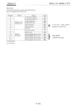
7.2.13

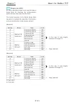
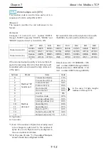
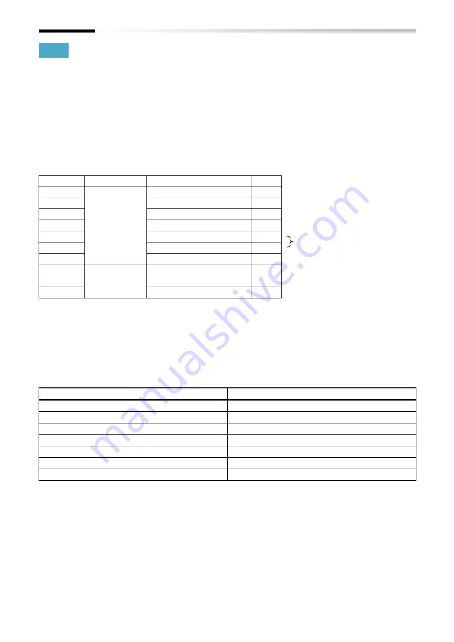
 Exception response 

The inverter returns a response to the request, but 
if an error occurs in the request, it is to return an 
exception response. 
 
[Exception response] 
(Example) 
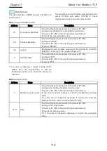
In case configuring nonexistent address to holding 
registers  using  the  Modbus  function  code  "03h 
(Read  holding  registers)",  it  is  to  return  the 
exception response shown below. 
 

Hi: high order 
Lo: low order


*1) When returning the exception response, being 

configured adding "80h" to the function code of 
the request. 


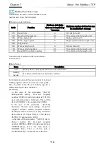
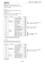
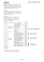
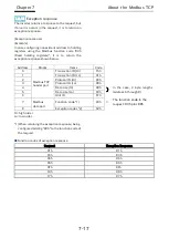
Function codes of exception response 


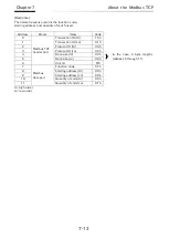
Address 

Blocks 

Items 

Code   


Modbus TCP 
header part 

Transaction ID (Hi) 

15h 


Transaction ID (Lo) 

01h 


Protocol ID (Hi) 

00h 


Protocol ID (Lo) 

00h 


Data size (Hi) 

00h 


In  the  case,  3  byte  lengths 
(address 6 through 8). 

Data size (Lo) 

03h 

Unit ID 

FFh 


Modbus   
data part 

Function code *1) 

83h 

← 

The function code in the 
request: 03h plus 80h 

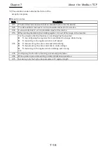
Exception codes *2) 

02h 


Request 

Exception Response 

01h 

81h 

03h 

83h 

05h 

85h 

06h 

86h 

0Fh 

8Fh 

10h 

90h 

17h 

97h 

Содержание SJ-P1 Series

Страница 1: ...he P1 EN 4 Enclosed Items 5 Installation and Configuration 6 Inverter Settings 7 About the Modbus TCP 8 FAQ and Troubleshooting 9 Specifications After reading this guide keep it handy for future reference When contacting us please let us know the following reference number Fundamental Required Verification The bookmark function is available in the electronic format ...

Страница 2: ...In Addition any personnel who handles or performs maintenance to the product must read carefully the inverter s Basic and User s Guide the P1 EN Basic Guide and this guide Before any attempt to install operate maintain or inspect this equipment a complete understanding of the equipment specifications safety instructions precautions handling and operation instructions is required Additionally perio...

Страница 3: ...itachi will be responsible for repairing or exchanging the previously exchanged or repaired part only during this warranty period In order to receive warranty service you should present the receipt issued by the product supplier or any other document that allow us to check the purchase date However any defects damage malfunction or any other failure caused by one of the following facts will not be...

Страница 4: ...e operating it remotely through the network Please verify that the Hitachi inverter is correctly configured and installed for the intended purpose in the designed system When using the Hitachi inverter please implement the following actions 1 Select an inverter with sufficient capacity for the rated current and performance 2 Implement safety design such as redundant system design 3 Implement safet...

Страница 5: ...o attach the P1 EN to the inverter Please refer to the Chapter 5 Installing and External Features 3 Installation Verify notes for the system configuration of the Ethernet Please refer to the Chapter 5 Installing and External Features 4 System Configuration Verify parameter settings of the inverter Please refer to the Chapter 6 Inverter settings 5 Parameter Settings Verify the LEDs that shows the s...

Страница 6: ...d Trademark Ethernet is a registered trademark of Xerox Corporation in the United States Document Name Document Code P1 EN Ethernet User s Guide this document NT254X P1 EN Ethernet Basic Guide NT2541X Document Name Inverter Document Code SJ series P1 User s Guide NT251 1 SJ series P1 Basic Guide NT2511 1 ...

Страница 7: ...ferrite cores 5 4 6 1 About this chapter 6 1 7 1 About this chapter 7 1 7 2 About the Modbus TCP 7 2 Table of Contents C 1 1 4 Precautions 1 3 1 5 Caution labels examples 1 7 2 4 Guide objectives 2 1 2 5 Guide outline 2 2 2 6 Symbol definition 2 3 3 3 Name plate 3 3 3 4 Dimensions after installed 3 3 4 3 Verification after the purchase 4 3 5 5 About the connection 5 5 5 6 External features 5 6 5 7...

Страница 8: ...1 About this chapter 8 1 8 2 Self diagnosis 8 2 9 1 About this chapter 9 1 8 3 Inverter troubleshooting 8 3 8 4 The LEDs and remedies 8 4 9 2 Device specifications 9 2 Chapter 8 FAQ and Troubleshooting Chapter 9 Specifications ...

Страница 9: ...C 3 Table of Contents Memo ...

Страница 10: ...s are categorized by degree of risk as Danger Warning and Caution The definition of each category is described below Danger This category warns the user that in case of an incorrect or improper handling it leads to a dangerous situation that have a high risk of causing death serious injuries and or major property damage Warning This category warns the user that in case of an incorrect or improper ...

Страница 11: ...this symbol indicates danger warning caution about ignition electric shock high temperature and others Inside or near the symbol the specific content will be shown This symbol indicates General hazard not specified be cautious This symbol indicates Electric shock hazard This symbol indicates prohibited actions Actions that should not be done when handling this device This symbol indicates actions ...

Страница 12: ...gas explosive gas flammable gas grinding fluid mist hydrogen sulfide or salt damage prone conditions Additionally it is recommended to install this device in ventilated room not exposed to direct sunlight Risk of injury DO NOT install or operate products with damage or missing parts In order to explain this device details the illustrations in this guide might show this device without covers Before...

Страница 13: ... failure Please handle the cables properly and DO NOT let them get damaged Using damaged cables will not only interfere with the correct operation of this device but also might be the cause of a system failure Risk of an electric shock and or injury Perform the wiring only after installing the inverter 1 For P1 00044 L to P1 01240 L P1 004L to P1 220L P1 00041 H to P1 00620 H P1 007H to P1 220H mo...

Страница 14: ...ange by the motor and or the equipment In case this device is being used to make the inverter produce high frequency outputs for a motor or other equipment make sure with the respective manufacturer that the motor or the equipment can tolerate the high frequency output given by the inverter During operation verify the motor rotation direction and that there are no irregular sounds or vibrations Ri...

Страница 15: ...to the precautions described above there are other precautions described in the chapter 8 of the inverter user s guide Please read and follow those precautions as well Entrust the maintenance inspection and or part replacement only to a specialized personnel Be sure to remove wristwatches and metal accessories e g bracelets before maintenance and inspection work and use insulated tools for the wor...

Страница 16: ...cases please use the label example on the right side as a reference Label template Please fill in the label and use it for preventing accidents Danger Warning Caution Label example For warning about automatically resumed operation after an error as a result of the retry function Danger Please DO NOT get close to the motor inverter or the system even if it is stopped It can restart suddenly after a...

Страница 17: ...1 8 Chapter 1 Safety Precautions Memo ...

Страница 18: ...ctives of this guide and its terminology 2 2 Applicable devices The contents of this guide will apply to the P1 EN device For information about the inverter please refer to the inverter s user s guide or the basic guide 2 3 Before reading this guide This guide is aimed for people who purchase handle install or connect control equipment design systems or manage factories This guide units are based ...

Страница 19: ...bout the items included with this device The chapter 5 Installing and Configuration Installing and Configuration contains information for installing and system configuring this device on the inverter The chapter 6 Inverter Settings Inverter Settings contains the explanation of the inverter parameters that relate with this device Chapter 7 About the Modbus TCP About the Modbus TCP contains the expl...

Страница 20: ...ring situations Hence in cases when an occurring situation is similar to a situation described in this guide it may be solved by using this guide information and the P1 EN functions Solution Answer Describes the settings and operations required in order to solve a particular problem or situation Precautions Describes the points of caution when using an indicated function This descriptions contain ...

Страница 21: ...2 4 Chapter 2 Overview Memo ...

Страница 22: ...3 2 3 3 Name plate 3 3 3 4 Dimensions after innstalled 3 3 3 1 About this chapter This chapter contains the explanation about this device external features and information on the name plate Symbol Definition Questions about a particular situation Solution Answer Precautions Q A 3 Chapter 3 About the P1 EN ...

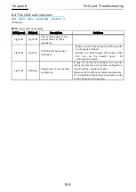
Страница 23: ...ow For installing this device or details of LEDs connectors and other parts refer to the chapter 5 Installation and Configuration The four LEDs over the RJ 45 connection don t turn on or blink Q A From the top RUN LED ERR LED LINK1 LED PORT 1 status LINK2 PORT 2 status Ethernet connector PORT 1 External power connector FG terminal Ethernet connector PORT 2 Name plate bottom ...

Страница 24: ...mensions after being installed The dimensions of this device after it is installed on the SJ P1 are shown in the image below As shown on the image a part of this device will stand out from the SJ P1 Please be cautious when installing the P1 EN Q A Q A Device model Manufacture number MFG No Factory control number SJ P1 inverter SJ P1 front surface View from the right side of the SJ P1 33mm 96 5mm ...

Страница 25: ...3 4 Chapter 3 About the P1 EN Memo ...

Страница 26: ...cation when unpacking 4 3 4 3 2 Read this guide 4 3 4 1 About this chapter This chapter contains information about the items enclosed with the P1 EN Additionally it is explained how to inspect and verify this product after its purchase Symbol Definition Questions about a particular situation Solution Answer Precautions Q A 4 Chapter 4 Enclosed Items ...

Страница 27: ...Ferrite core specification Contact your sales agent immediately in case there are defects or imperfections The enclosed items are shown on the images below Item Name Manufacturer Model Inner Diameter Ferrite Core SEIWA ELECRIC MFG Co Ltd E04SR200935A 9mm Q A P1 EN x1 Basic Guide x1 Ferrite Core x2 ...

Страница 28: ...on necessary to handle the P1 EN correctly Read it carefully and keep it safe Also use the inverter user s guide and basic guide as a reference Please make sure that the P1 EN basic guide and the inverter basic guide reach the end user Additionally advice the end user to download and read the latest version of this guide Q A Check that the items were not smashed or damaged during the delivery Chec...

Страница 29: ...4 4 Chapter 4 Enclosed Items Memo ...

Страница 30: ...2 Ethernet cable specifications 5 6 5 6 3 External power supply optional 5 7 5 6 4 LED 5 7 5 7 System Configuration 5 8 5 1 About this chapter This chapter contains information for installing and system configuring this device on the inverter For information about the inverter installation please refer to the inverter user s guide Additionally when doing any work or operation always follow the saf...

Страница 31: ...o the right If the version is 2 00 or higher it can support the P1 EN 5 3 Installation 5 3 1 About the installation The P1 EN can be attached to any of the 3 option slots of the SJ P1 Option cassette connection slots VOP keypad RJ45 USB micro B SLOT1 SLOT2 SLOT3 It can be attached to either SLOT1 2 or 3 Model P1 00330 LFF Hitachi Industrial Equipment Systems Co Ltd MADE IN JAPAN Ver 2 00 INVERTER ...

Страница 32: ...cover will no longer be needed it is recommended to keep it in a safe place However the screw that secured the cover will be used to secure the P1 EN 2 Attach this device The slots 2 and 3 have one more connection in the lower side However the P1 EN will not need that connection Option cassette connection slots VOP keypad RJ45 USB micro B SLOT1 SLOT2 SLOT3 Remove the screw and then remove the cove...

Страница 33: ...cannot be correctly fixed to the cable and it may slip along the cable despite having an anti slip claw In these cases the ferrite core can be fixed by attaching something like a clamping band or a wire to the Ethernet cable on one or both sides of the ferrite core Keep in mind that the cores should be attached as close as possible to the P1 EN RJ 45 connection Option cassette connection slots VOP...

Страница 34: ...upply 2 Allocate function like free run or reset to the inverter input terminals accordingly when the master detects a connection abnormality it turns on these terminals 3 Configure the inverter so in case of a connection abnormality it stops free run stops or trip When the operation command is received through Ethernet the inverter shipment settings are configured so that if there is any abnormal...

Страница 35: ...e cable for the connecting devices Namely it is necessary for proper communication between the devices to use distinguished the cable of straight type or cross type The connection is available Ethernet connectors conformed with 10BASE T 100BASE TX The distance between the nodes the devices should be within 100 meters Connector Type Notes RJ 45 The electric characteristics conform with the IEEE802 ...

Страница 36: ...n off It can always be supplied by the external power source When using the external power connect the cable so it minimizes the tension and stress over the connector External power source specification DC24V 10 and 2A or more are required LED Color Description RUN Green Light off P1 EN initializing Blinking Link in preparation Light on Link established the Ethernet communication ERR Red Light off...

Страница 37: ...f procedure as shown in 5 5 About the connection In case of configuring a system that the inverter operates immediately at powered on please consider to take about 1 minute for the link established Function the network hub PORT1 and PORT2 are available as network hub shown in above example 2 if the inverter is powered The only problem that the inverter can detect related to the Ethernet connection...

Страница 38: ...evice and the client higher level device correlating parameters 6 2 6 2 3 Inverter and P1 EN correlating parameters 6 6 6 2 4 Other parameters 6 7 6 1 About this chapter This chapter contains the information about the inverter settings that must be done when using the P1 EN Symbol Definition Precautions 6 Chapter 6 Inverter Settings ...

Страница 39: ...d in this device when the inverter is powered on Make sure to restart the inverter after configuring the parameters Code Parameter name Selection Initial value oH 01 IP address selection 00 Gr 1 01 Gr 2 00 oH 02 Communication speed PORT1 00 Auto Negotiation 01 100M Full duplex 02 100M Half duplex 03 10M Full duplex 04 10M Half duplex 00 oH 03 Communication speed PORT2 00 Auto Negotiation 01 100M F...

Страница 40: ... 2 0 255 0 oL 43 IPv4 IP address 4 Gr 2 0 255 2 oL 44 IPv4 sub net mask 1 Gr 2 0 255 255 oL 45 IPv4 sub net mask 2 Gr 2 0 255 255 oL 46 IPv4 sub net mask 3 Gr 2 0 255 255 oL 47 IPv4 sub net mask 4 Gr 2 0 255 0 oL 48 IPv4 default gateway 1 Gr 2 0 255 192 oL 49 IPv4 default gateway 2 Gr 2 0 255 168 oL 50 IPv4 default gateway 3 Gr 2 0 255 0 oL 51 IPv4 default gateway 4 Gr 2 0 255 1 oL 60 IPv6 IP addr...

Страница 41: ...le to be configured from 1024 to 65535 Although as standard specification the Modbus TCP port number generally sets in 502 oH 05 in the case of using the IPv4 oH 06 in the case of using the IPv6 oL 01 oL 04 IPv4 IP address 1 4 Gr 1 oL 20 oL 27 IPv6 IP address 1 8 Gr 1 oL 40 oL 43 IPv4 IP address 1 4 Gr 2 oL 60 oL 67 IPv6 IP address 1 8 Gr 2 These parameters can configure the IP address of the Ethe...

Страница 42: ...Gr 2 oL 69 oL 76 IPv6 default gateway 1 8 Gr 2 These parameters can configure the default gateway of the Ethernet communication oL 09 to oL 12 in case of using the group 1 and the IPv4 oL 29 to oL 36 in case of using the group 1 and the IPv6 oL 48 to oL 51 in case of using the group 2 and the IPv4 oL 69 to oL 76 in case of using the group 2 and the IPv6 ...

Страница 43: ...re recommended oA 13 Run command selection at start up SLOT 1 oA 23 Run command selection at start up SLOT 2 oA 23 Run command selection at start up SLOT 3 These parameters can select whether to execute run commands or not while this device and the inverter communication is being established Do not execute 00 run command disabled Execute 01 run command enabled Please make sure to configure the par...

Страница 44: ...his device please select the 00 A V setting oA 11 Communication Watch Dog Timer SLOT 1 oA 21 Communication Watch Dog Timer SLOT 2 oA 31 Communication Watch Dog Timer SLOT 3 This setting is unavailable for this device Please do not change the setting oA 12 Action selection at communication error SLOT 1 oA 22 Action selection at communication error SLOT 2 oA 32 Action selection at communication erro...

Страница 45: ...6 8 Chapter 6 Inverter Settings Memo ...

Страница 46: ...r 06h 7 10 7 2 9 Diagnostics 08h 7 11 7 2 10 Write multiple coils 0Fh 7 12 7 2 11 Write multiple registers 10h 7 14 7 2 12 Read Write multiple registers 17h 7 15 7 2 13 Exception response 7 17 7 3 Conection with the ProDriveNext 7 19 7 1 About this chapter This chapter contains information for the Modbus TCP communication The P1 EN is a server device that uses Modbus TCP communication via the netw...

Страница 47: ...nsmission speed Fixed transmission speed 10Mbps Full Half duplex or 100Mbps Full Half duplex 1 Auto detection transmission speed Auto negotiation 1 Auto MDI X According to selection of communication method transmission speed it is to be configured as follows Selecting the auto negotiation the function Auto MDI X is available Selecting others the function Auto MDI X is unavailable Communication pro...

Страница 48: ...EN Configure 0000h The server P1 EN to the client higher level device It returns 0000h 4 5 Length Configure the size of datas united Unit ID address 6 and PDU address 7 to N unit the number of bytes 1 6 Unit Identifier The client higher level device to the server P1 EN Configure FFh The server P1 EN to the client higher level device It returns FFh Address Items Description 7 Modbus function code T...

Страница 49: ...1 A hence the data scale is 10 times That is if the data is 25 0 A it is expressed as 250d In the case of the parameter Hb110 Async Motor constant R1 1st motor register number 3B06h to 3B07h its data resolution is 0 000001 ohm hence the data scale is 1000000 times That is if the data is 0 149378 ohm it is expressed as 149378d Code Function Maximum data bytes that can be handled by 1 message Maximu...

Страница 50: ...000Fh Hi high order Lo low order Address Blocks Items Code 0 Modbus TCP header part Transaction ID Hi 15h 1 Transaction ID Lo 01h 2 Protocol ID Hi 00h 3 Protocol ID Lo 00h 4 Data size Hi 00h In the case 6 byte lengths address 6 through 11 5 Data size Lo 06h 6 Unit ID FFh 7 Modbus data part Function code 01h 8 Starting adderess Hi 00h In the case 0000h 0001h minus 1 9 Starting adderess Lo 00h 10 Qu...

Страница 51: ... is not a multiple of eight the remaining bits in the final data byte will be padded with zeros toward the high order end of the byte By convention bits within a byte are shown with the MSB to the left and the LSB to the right Address Blocks Items Code 0 Modbus TCP header part Transaction ID Hi 15h 1 Transaction ID Lo 01h 2 Protocol ID Hi 00h 3 Protocol ID Lo 00h 4 Data size Hi 00h In the case 5 b...

Страница 52: ...rips 03E9h through 03EDh from the inverter Hi high order Lo low order Address Blocks Items Code 0 Modbus TCP header part Transaction ID Hi 15h 1 Transaction ID Lo 01h 2 Protocol ID Hi 00h 3 Protocol ID Lo 00h 4 Data size Hi 00h In the case 6 byte lengths address 6 through 11 5 Data size Lo 06h 6 Unit ID FFh 7 Modbus data part Function code 03h 8 Starting adderess Hi 03h In the case 03E8h 03E9h min...

Страница 53: ...nsaction ID Lo 01h 2 Protocol ID Hi 00h 3 Protocol ID Lo 00h 4 Data size Hi 00h In the case 13 byte lengths address 6 through 18 5 Data size Lo 0Dh 6 Unit ID FFh 7 Modbus data part Function code 03h 8 Byte count 1 0Ah 9 Redister value 1 Hi 00h 0003h 03d E03 factor over current 10 Redister value 1 Lo 03h 11 Redister value 2 Hi 00h 0000 04D2h 1234d 12 34 Hz output frequncy 12 Redister value 2 Lo 00h...

Страница 54: ...eader part Transaction ID Hi 15h 1 Transaction ID Lo 01h 2 Protocol ID Hi 00h 3 Protocol ID Lo 00h 4 Data size Hi 00h In the case 6 byte lengths address 6 through 11 5 Data size Lo 06h 6 Unit ID FFh 7 Modbus data part Function code 05h 8 Starting adderess Hi 00h In the case 0000h 0001h minus 1 9 Starting adderess Lo 00h 10 Output value Hi FFh FF00h to be ON 11 Output value Lo 00h Address Blocks It...

Страница 55: ...D Hi 15h 1 Transaction ID Lo 01h 2 Protocol ID Hi 00h 3 Protocol ID Lo 00h 4 Data size Hi 00h In the case 6 byte lengths address 6 through 11 5 Data size Lo 06h 6 Unit ID FFh 7 Modbus data part Function code 06h 8 Starting adderess Hi 2Fh In the case 2F4Dh 2F4Eh minus 1 9 Starting adderess Lo 4Dh 10 Register vaule Hi 13h 1388h 5000d 50 00 Hz frequency 11 Register value Lo 88h Address Blocks Items ...

Страница 56: ...nsaction ID Lo 01h 2 Protocol ID Hi 00h 3 Protocol ID Lo 00h 4 Data size Hi 00h In the case 6 byte lengths address 6 through 11 5 Data size Lo 06h 6 Unit ID FFh 7 Modbus data part Function code 08h 8 Sub function Hi 00h 9 Sub function Lo 00h 10 Data Hi XXh freely selected 11 Data Lo XXh Address Blocks Items Code 0 Modbus TCP header part Transaction ID Hi 15h 1 Transaction ID Lo 01h 2 Protocol ID H...

Страница 57: ...alue should be configured to 00h By convention bits within a byte are shown with the MSB to the left and the LSB to the right Output value Hi 01000000b 40h coil number 0008h through 0001h Output value Lo 00010010b 12h coil number 000Fh through 0009h Bit7 Bit6 Bit5 Bit4 Bit3 Bit2 Bit1 Bit0 Output value Hi 0008h 0007h 0006h 0005h 0004h 0003h 0002h 0001h OFF 0 ON 1 OFF 0 OFF 0 OFF 0 OFF 0 OFF 0 OFF 0...

Страница 58: ...locks Items Code 0 Modbus TCP header part Transaction ID Hi 15h 1 Transaction ID Lo 01h 2 Protocol ID Hi 00h 3 Protocol ID Lo 00h 4 Data size Hi 00h In the case 6 byte lengths address 6 through 11 5 Data size Lo 06h 6 Unit ID FFh 7 Modbus data part Function code 0Fh 8 Starting address Hi 00h 9 Starting address Lo 00h 10 Quantity of coils Hi 00h 11 Quantity of coils Lo 0Fh ...

Страница 59: ... 3 Protocol ID Lo 00h 4 Data size Hi 00h In the case 6 byte lengths address 6 through 11 5 Data size Lo 0Bh 6 Unit ID FFh 7 Modbus data part Function code 10h 8 Starting adderess Hi 2Bh In the case 2B01h 2B02h minus 1 9 Starting adderess Lo 01h 10 Quantity register Hi 00h 11 Quantity register Lo 02h 12 Byte count 1 04h 13 Register value 1 Hi 00h 0000 03E8h 1000d 10 00 s 14 Register value 1 Lo 00h ...

Страница 60: ...s to actually change not the number of hold registers Address Blocks Items Code 0 Modbus TCP header part Transaction ID Hi 15h 1 Transaction ID Lo 01h 2 Protocol ID Hi 00h 3 Protocol ID Lo 00h 4 Data size Hi 00h In the case 15 byte lengths address 6 through 20 5 Data size Lo 0Fh 6 Unit ID FFh 7 Modbus data part Function code 17h 8 Read starting address Hi 2Bh In the case 2B03h 2B04h minus 1 9 Read...

Страница 61: ... part Transaction ID Hi 15h 1 Transaction ID Lo 01h 2 Protocol ID Hi 00h 3 Protocol ID Lo 00h 4 Data size Hi 00h In the case 7 byte lengths address 6 through 12 5 Data size Lo 07h 6 Unit ID FFh 7 Modbus data part Function code 17h 8 Byte count 04h 9 Read register value 1 Hi 00h 0000 0BB8h 3000d 30 00 s 10 Read register value 1 Lo 00h 11 Read register value 2 Hi 0Bh 12 Read register value 2 Lo B8h ...

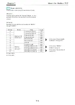
Страница 62: ... order Lo low order 1 When returning the exception response being configured adding 80h to the function code of the request Function codes of exception response Address Blocks Items Code 0 Modbus TCP header part Transaction ID Hi 15h 1 Transaction ID Lo 01h 2 Protocol ID Hi 00h 3 Protocol ID Lo 00h 4 Data size Hi 00h In the case 3 byte lengths address 6 through 8 5 Data size Lo 03h 6 Unit ID FFh 7...

Страница 63: ...r it is out of the range in the inverter 22h It is the situation that the function is not allowed by the inverter To be configuring the register that is prohibited to change while driving To be writing to the register which is soft locked To be executing the enter command while driving To be executing the enter command in under voltage To be writing to the register while operating auto tuning etc ...

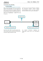
Страница 64: ...pecifications needed for the connection Attach the the P1 EN to any of the option slots of the inverter then connect the P1 EN and the computer using the Ethernet cable Functions such as the wizard function parameter file read write function inverter progam create download function and trace function become available when using the ProDriveNext For detailed information regarding the ProDriveNext p...

Страница 65: ...7 20 Chapter 7 About the Modbus TCP Memo ...

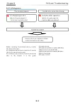
Страница 66: ...This chapter contains the troubleshooting of cases such as errors detected by the protection function warnings given by the warning function or some cases in which the device is not working properly When the device is not working properly or there is any trouble read this chapter before trying to solve the problem Use the following sections as a reference when dealing with these situations Symbol ...

Страница 67: ...his guide 1 Inverter model 2 Inverter manufacture number MFG No 3 Option device model P1 EN 4 Option manufacture number MFG No 5 Date of purchase 6 Inquiry contents It is displaying an error Refer to this guide page 8 3 8 3 Inverter troubleshooting The inverter tripped The ERR LED is turned ON or blinking Verify the LEDs operation Refer to this guide page 8 6 8 4 The LEDs and solutions Cannot be s...

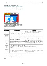
Страница 68: ... It may have been damaged that the connector connecting this device to the inverter Please exchange the device Allocated the function Reset to the inverter input terminal so when the terminal may be turned on Verify the inverter parameters configuring SLOT 1 E060 E069 SLOT 2 E070 E079 SLOT 3 E080 E089 Fatal abnormality occurred in this device when powered on or operating Turn off the inverter then...

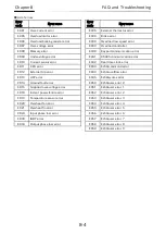
Страница 69: ...0 Overheat fan error E021 Overheat fin error E024 Input phase loss error E030 IGBT error E034 Output phase loss error Error code Error name E035 External thermistor error E036 Brake error E038 Overload low speed error E039 Overload controller E040 Keypad communication error E041 RS485 communication error E042 Real time clock error E043 EzSQ command error E044 EzSQ overflow error E045 EzSQ syntax e...

Страница 70: ...n2 error 8 E079 Option2 error 9 E080 Option3 error 0 E081 Option3 error 1 E082 Option3 error 2 E083 Option3 error 3 E084 Option3 error 4 E085 Option3 error 5 E086 Option3 error 6 E087 Option3 error 7 E088 Option3 error 8 E089 Option3 error 9 Error code Error name E090 STO active error E091 STO D error E092 STO 1 error E093 STO 2 error E094 FS option D error E095 FS option 1 error E096 FS option 2 ...

Страница 71: ...EN might have been damaged Make sure that this product and the inverter are properly attached Detach and attach again this device After this turn on the inverter again Or exchange the device Light off Blinking Setting error in the inverter configuring It may be unmatched between the inverter setting parameters and system configuration e g IP address configuring etc Please verify the Ethernet relat...

Страница 72: ...Chapter 9 Specifications 9 Chapter 9 Specifications Contents 9 1 About this chapter 9 1 9 2 Device Specifications 9 2 9 1 About this chapter This chapter contains information about the P1 EN specifications ...

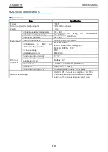
Страница 73: ...Hz Conformance to EMC and electrical safety standards IEC EN61800 3 Second environment Category C3 IEC EN61800 5 1 SELV Enclosure rating IP00 Ethernet Interface Applicable standards IEEE 802 3 Communication protocol TCP IP Communication protocol application layer Modbus TCP Physical layer 10BASE T 100BASE TX IEEE802 3 Connector RJ45 PORT1 PORT2 Communication distance Distance between nodes 100 m m...

Отзывы: