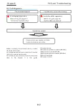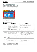
7-8
Chapter 7
About the Modbus TCP
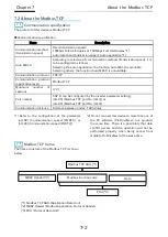
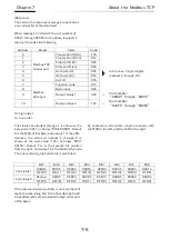
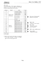
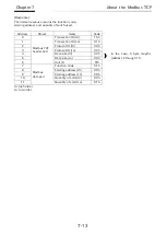
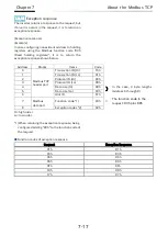
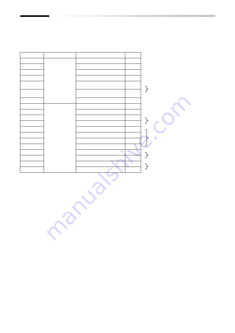
[Response]
The register data in the response message are
packed as two bytes per register, with the binary
contents right justified within each byte.
Hi: high order
Lo: low order
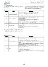
*1) Data for the number of data bytes is transferred.
In the above example, it returns 10 ("0Ah")
bytes for five holding register data.
Address
Blocks
Items
Code
0
Modbus TCP
header part
Transaction ID (Hi)
15h
1
Transaction ID (Lo)
01h
2
Protocol ID (Hi)
00h
3
Protocol ID (Lo)
00h
4
Data size (Hi)
00h
In the case, 13 byte lengths
(address 6 through 18).
5
Data size (Lo)
0Dh
6
Unit ID
FFh
7
Modbus
data part
Function code
03h
8
Byte count *1)
0Ah
9
Redister value 1 (Hi)
00h
0003h→03d
→E03(factor: over current)
10
Redister value 1 (Lo)
03h
11
Redister value 2 (Hi)
00h
0000 04D2h
→1234d→12.34[Hz]
(output frequncy)
12
Redister value 2 (Lo)
00h
13
Redister value 3 (Hi)
04h
14
Redister value 3 (Lo)
D2h
15
Redister value 4 (Hi)
00h
001Eh→30d→3.0[A] (current)
16
Redister value 4 (Lo)
1Eh
17
Redister value 5 (Hi)
01h
011Ch→284d
→284[V] (DC voltage)
18
Redister value 5 (Lo)
1Ch
Содержание SJ-P1 Series
Страница 9: ...C 3 Table of Contents Memo ...
Страница 17: ...1 8 Chapter 1 Safety Precautions Memo ...
Страница 21: ...2 4 Chapter 2 Overview Memo ...
Страница 25: ...3 4 Chapter 3 About the P1 EN Memo ...
Страница 29: ...4 4 Chapter 4 Enclosed Items Memo ...
Страница 45: ...6 8 Chapter 6 Inverter Settings Memo ...
Страница 65: ...7 20 Chapter 7 About the Modbus TCP Memo ...

