15
INSTALLATION AND OPERATION MANUAL
ENGLISH
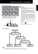
ATTENTTION:
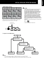
In the case where the group setting fails to complete normally,
check to ensure that the following items are satisfied and perform
the group setting by the centralized ON/OFF controller again.
-
The central station is connected to the same H-LINK (Control
Line) system where the centralized ON/OFF controller is
connected.
-
The power is distributed to the central station and the liquid
crystal display is appeared.
-
The address of the central station is No. 0 (DSW1-1 to 3 pin:
OFF).
-
The group setting is performed for Zone 1 of the central station
No. 0 (main unit and slave unit).
CAUTION:
-
The remote control switch is required to control indoor units by
the centralized ON/OFF controller.
-
The remote control switch is required when other centralized
controller is used together.
-
The operation by the centralized ON/OFF controller is not
available during the process of group setting.
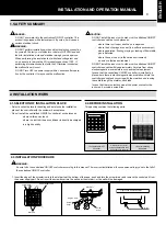
5. SCHEDULE CONTROL FUNCTION
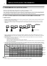
The centralized ON/OFF controller, connecting to the control timer, can
control the running schedule of "RUN/STOP" operation three times a
day for a week.
The "RUN/STOP" operation is controlled simultaneously, and the
schedule control for each group is not available.
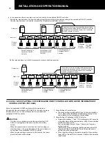
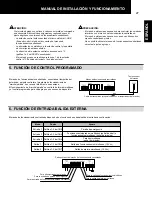
Control timer
Centralized ON/OFF Controller
Transmission cable (Provided with Control Timer)
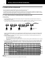
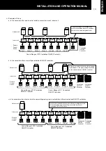
6. EXTERNAL INPUT/OUTPUT FUNCTION
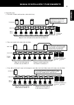
The centralized ON/OFF controller has two input / output function shown as below:
Mode
Port
Setting
Input 1
CN2 1-2 Pin
Emergency Stop
Input 2
CN4 2-3 Pin
Simultaneous Operation / Stoppage (Level Signal) or
Simultaneous Operation (Pulse Signal)
Input 3
CN4 1-2 Pin
Simultaneous Stoppage
(Pulse Signal)
Output 1
CN6 1-3 Pin
Simultaneous Operation Output (DC12V)
Output 2
CN7 1-3 Pin
Simultaneous Alarm Output (DC12V)
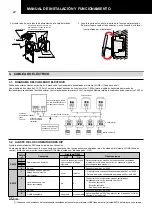
Back of Centralized ON/OFF Controller
For control timer
For Emergency Stoppage Input
For Simultaneous Operation/Stoppage Input
For Simultaneous Operation Output
For Simultaneous Alarm Output


