12
INSTALLATION AND OPERATION MANUAL
4. GROUP SETTING PROCEDURE
-
For group setting with the centralized ON/OFF controller, the remote control switch is required.
When using with other centralized controllers, the remote control switch is also required.
-
In case that there are indoor units with auto-louver and indoor units without auto-louver in the same group, the address of the smaller number in
the remote control switch group shall be applied for the indoor units with auto-louver. If the address of the smaller number is applied for the indoor
units without auto-louver, the setting of auto-louver is not available for the remote control switch group.
4.1. CASE 1: GROUP SETTING BY CENTRALIZED ON/OFF CONTROLLER ALONE
¡
Group Setting
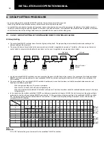
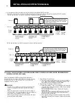
a. The centralized ON/OFF controller has no function of group setting itself. The group setting is automatically performed according to the
address setting of the indoor unit.
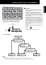
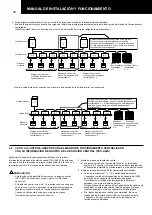
b. The group of indoor units controlled by the same remote control switch is regarded as one group. Therefore, in the case where the remote
control switch is connected individually with each indoor unit, one unit is regarded as one group as shown below.
Group 1
Group 2
Group 3
Group 4
Remote Control
Switch
I.U. Add
Ref. Add.
c. Up to 8 centralized ON/OFF controllers can be connected to the same H-LINK (Control Line) system. For connection of multiple centralized
ON/OFF controllers, provide address for each centralized ON/OFF controller by setting the dip switch (SW18) inside of the centralized ON/
OFF controller.
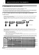
d. The group setting of the centralized ON/OFF controller is performed in order, from the indoor unit with the smallest address number, and
finished on the following conditions.
−
When the group setting up to 16 groups is completed.
−
When there is no indoor unit in the same refrigerant cycle.
−
When the serial numbered address of the indoor unit breaks off, and there are indoor units with continued address number in the same
refrigerant cycle.
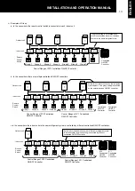
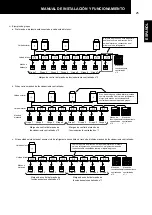
e. In the case where the multiple centralized ON/OFF controllers are connected in the same H-LINK (Control Line) system, the group setting is
performed in order from the centralized ON/OFF controller No. 0. After completion of the group setting of the centralized ON/OFF controller
No. 0, the group setting of the centralized ON/OFF controller No. 1 is started, and the group setting is continued in order of the number of
centralized ON/OFF controller.
I.U. Add.
Ref. Add.
0
1
2
3
4
5
6
7
8
9
10
11
12
13
14
15
16
17 18 19 ...
0
G1
G4 G5 G6 G7 G8
1
G9 G10 G11 G12 G13 G14 G15 G16 G1
G2
2
G3
G4
G5
G6
G7
G8
G9 G10
3
4
G1
G2
G3
G4
G5
G6
G7
G8
5
G9 G10 G11 G12
G1
G2
G3
G4
G5
G6
6
G7
G8
...
NOTE:
“G1 to G16” indicates the group number set for the centralized ON/OFF controllers.
No.0
Centralized
ON/OFF
Controller
No.1
Centralized
ON/OFF
Controller
No.2
Centralized
ON/OFF
Controller
No.3
Centralized
ON/OFF
Controller
G2
Remocon Group
G3
Remocon Group


