


--- 16 ---
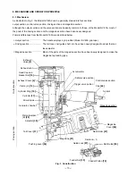
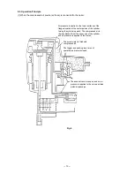
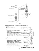
Fig. 7
The pressure on the upper surface of the exhaust valve is released, and
the exhaust valve is pushed upward by the air pressure within the
cylinder. This opens the exhaust vent, and the air pressure in the cylinder
and the left-side surface of the feed piston are discharged from the nailer.
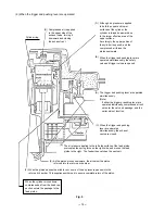
Air pressure is discharged from the upper end of the
cylinder, and the cylinder is pushed upward by the air
pressure on the lower surfaces of the flanges and the
force of the springs. This closes the upper end of the
cylinder, and blocks further compressed air from
entering the cylinder.
At the time the piston returns, any remaining air
pressure at the lower end of the piston is
discharged through the clearance between the
tail cover and the driver blade.
When the air pressure at the upper side of the piston is reduced, the
air pressure within the return air chamber pushes the piston upward.
(Note) If the clearance were any larger, the piston
would not return: if it were smaller, driving
force would be decreased.
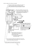
When the trigger is released, the trigger valve
closes, and the compressed air does not flow
into the air passage. The air pressure within
the valve air passage is discharged through valve
exhaust vent I .
In addition, when the pushing lever is lifted from
the wood surface, the safety valve closes and
the air pressure within the valve air passage is
discharged through valve exhaust vent II .
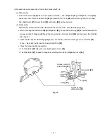
(The illustration shows both the trigger and
pushing lever released.)
Valve exhaust vent II
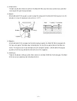
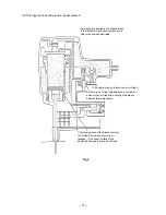
(4) When the trigger and/or pushing lever are released:
As the air pressure at the left-side surface of the feed piston is reduced, spring
force at the right-side surface moves the feed piston toward the ejecting gate, and
the next nail is fed into firing position by the feeder.
(C)
(B)
Valve exhaust vent I
(A)
(E)
(F)
(D)