--- 30 ---
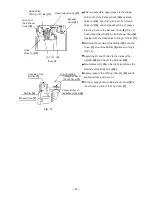
Fig. 24
Latch
[27]
Window of Pushing
Lever (B)
[30]
End surface of Pushing Lever (A)
[40]
(b) Reassembly
Proceed in reverse to the disassembly procedure, taking care of the following points.
Before reassembly, check that the end surface of Pushing Lever (A)
[40]
is fitted in the opening of the
Pushing Lever Guide
[28]
(Fig. 23).
After reassembly, check that Pushing Lever (A)
[40]
operates smoothly.
Fig. 23
Opening of the Pushing Lever
Guide
[28]
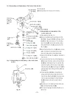
(2) Disassembly and reassembly of the adjuster
(a) Disassembly
Remove the Roll Pin D1.6 x 12
[68]
. Then the Adjuster Knob
[69]
, the Adjuster Spring
[67]
, the Bolt Washer
M4
[66]
, the Latch
[27]
, the Adjuster Shaft
[26]
, the Spring
[29]
, Pushing Lever (B)
[30]
and the Adjuster
[70]
can be removed.
(b) Reassembly
Proceed in reverse to the disassembly procedure, taking care of the following points.
Align the dihedral width portion and the radius portion of the Latch
[27]
to the window of Pushing Lever (B)
[30]
when reassembling (Fig. 24).
Mount the Adjuster
[70]
and the Adjuster Knob
[69]
as shown below (Fig. 25).
Apply the provided oil (SHELL TONNA S32 Oil) to Pushing Lever (B)
[30]
and the Bolt Washer M4
[66]
before reassembly.
After reassembly, check that the Adjuster
[70]
and Pushing Lever (B)
[30]
operate smoothly.
Adjuster
[70]
Mount the Adjuster
Knob
[69]
in this
orientation.
Fig. 25
Radius
portion
Dihedral
width
portion
Содержание NV 50AF3
Страница 41: ......


