--- 36 ---
(b) Reassembly
Reassembly can be accomplished by following the disassembly procedures in reverse. However, special
attention should be given to the following items.
Prior to reassembly, thoroughly remove any tar or dirt which may be stuck on the Guard [31] or on the
sliding portion of the Feeder (A) [70].
Assemble the Feeder Shaft Ring [72] onto the Feeder Shaft [71] so that the chamfered inner surface is
facing toward the Feeder Spring [69] side.
Ensure that the hooked portions at both ends of the Feeder Spring [69] are properly inserted into the
provided grooves on Feeder (A) [70].
Prior to reassembly, coat grease on the O-Ring (P-9) [61], the Feed Piston O-Rings [62] [64], and the
O-Ring sliding portions of the Feed Piston [63] and Nose [32]. However, as excessive grease will cause
improper movement of the Feed Piston [63], be very careful during grease application. (This is particularly
important if the tool is to be used at relatively low air pressures.)
Carefully clean the air passage of the Nose [32]. Any dust or foreign matter in the air passage will cause
malfunction of the Feed Piston [63].
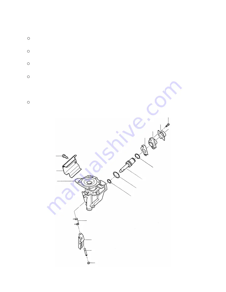
Gasket (E) [65]
Feed Piston Cover [66]
O-Ring (P-9) [61]
Feed Piston [63]
Hex. Socket Hd. Bolt
M5 x 10 [68]
Magazine Bushing [67]
Nose [32]
Guard [31]
Hex. Socket Hd.
Bolt M5 x 8 [30]
Feeder Shaft Ring [72]
Feeder Shaft [71]
Feeder (A) [70]
Feeder Spring [69]
Feed Piston O-Ring (I.D. 14) [62]
Feed Piston O-Ring (I.D. 11) [64]
Fig. 22
Содержание NV 45AB2
Страница 24: ... 21 9 2 Possible Causes and Corrections of Air Leakage Air leakage repair location Fig 8 ...
Страница 48: ......


