--- 29 ---
(b) Reassembly
Reassembly can be accomplished by following the disassembly procedures in reverse. However, special
attention should be given to the following items.
Assemble Piston (H) [13] so that its semi-circular grooved side is facing toward the Magzine side. (Same
as paragraph 10-2-(1)-(b))
Ensure that the air vent holes on Gasket (F) [8] are properly aligned with the matching holes in Body Ass'y [24].
(3) Head Cap [11] and related parts: (See Fig. 12.)
(a) Disassembly:
Remove Exhaust Cover [11]. (Refer to paragraph 10-2-(2).)
Remove the two Hex. Socket Hd. Bolts M5 x 25 [1] and disassemble Head Cap [11], Exhaust Valve [10]
and Gasket (G) [9].
(b) Reassembly:
Reassembly can be accomplished by following the disassembly procedures in reverse. However, special
attention should be given to the following items.
Ensure that the air vent holes in Gasket (G) [9] are properly aligned with the matching holes in Head Cap
[11] and Exhaust Cover (B) [4].
(4) Grip Rubber
The Grip Rubber [41] assembled in the Body Ass'y [24] is not supplied singly because the disassembly and
reassembly are not easy. When replacement of the Grip Rubber [41] is required, replace the Body Ass'y [24]
(Body Ass'y [24] comes with the Grip Rubber [41]) or install grip tape (A) according to the following procedure.
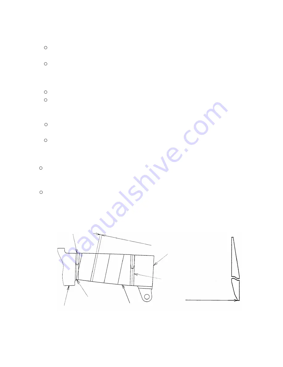
Installation of grip tape (A) and tape
Adhere the adhesive-backed grip tape (A) and the tape to the Body Ass'y [24]. First, adhere the end of grip
tape (A) under the trigger valve of the Body Ass'y [24] and wind around the Body Ass'y [24]. Wind the Tape at
both ends of grip tape (A) (see Fig. 14). Be careful that grip tape (A) and tape cannot be removed once they
are adhered.
Fig. 14
Grip tape (A)
End of grip tape (A)
Body Ass'y [24]
Trigger valve
Winding amount: 1.5 - 3 mm
(0.06 - 0.12")
End of grip tape (A)
Tape
Tape
Содержание NV 45AB2
Страница 24: ... 21 9 2 Possible Causes and Corrections of Air Leakage Air leakage repair location Fig 8 ...
Страница 48: ......


