


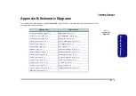


Schematic Diagrams
Montara GM-1 (71-M3000-D04) B - 5
B.Sch
em
atic D
iag
rams
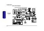
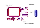
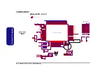
Montara GM-1
Sheet 4 of 29
Montara GM-1
+2.5V
+1.5VS
+2.5V
+2.5V
+2.5V
+1.5VS
+1.5VS
+3VS
+1.5VS
+3VS
M_DATA[63:0]
[9]
M_CB[7:0]
[9]
M_DQS[8:0] [9]
M_AA0
[8,9]
M_AA[2:1] [8,9]
M_AA3
[8,9]
M_AA[12:6] [8,9]
M_AA[5:4] [8,9]
M_AB[2:1] [8,9]
M_AB[5:4] [8,9]
M_CKE0
[8,9]
M_CKE1
[8,9]
M_CKE2
[8,9]
M_CKE3
[8,9]
M_CS0#
[8,9]
M_CS2#
[8,9]
M_CS3#
[8,9]
M_BS0#
[8,9]
M_BS1#
[8,9]
M_RAS#
[8,9]
M_CAS#
[8,9]
M_WE#
[8,9]
M_CLK_DDR0 [8]
M_CLK_DDR0# [8]
M_CLK_DDR1 [8]
M_CLK_DDR1# [8]
M_CLK_DDR2 [8]
M_CLK_DDR2# [8]
M_CLK_DDR3 [8]
M_CLK_DDR3# [8]
M_CLK_DDR4 [8]
M_CLK_DDR4# [8]
M_CLK_DDR5 [8]
M_CLK_DDR5# [8]
M_DM[8:0] [9]
M_CS1#
[8,9]
DVOBCINTRB
[27]
DVOBCCLKINT
[27]
ADDDETECT
[6]
AGP_BUSY#
[13]
CLK_MCH66
[10]
DAC_BLUE [11]
DAC_GREEN [11]
DAC_RED [11]
DAC_HSYNC [11]
DAC_VSYNC [11]
DAC_DDCACLK [11]
DAC_DDCADATA [11]
LVDS-L0N [11]
LVDS-L1N [11]
LVDS-L2N [11]
LVDS-L0P [11]
LVDS-L1P [11]
LVDS-U0N [11]
LVDS-U1N [11]
LVDS-U2N [11]
LVDS-U0P [11]
LVDS-U1P [11]
LVDS-U2P [11]
LVDS-LCLKN [11]
LVDS-UCLKN [11]
LVDS-UCLKP [11]
ENAVDD
[11]
DREFCLK [10]
DREFSSCLK [10]
LCLKCTLA [10]
LCLKCTLB [6,10]
H_DPSLP# [3,12,28]
PCIRST# [6,12,16,17,18,19,20,21,24,27]
PG_VGATE [13,28]
LVDS-L2P [11]
LVDS-LCLKP [11]
MI2CCLK
[27]
MI2CDATA
[27]
DVOCD[11:0]
[27]
DVOCCLK
[27]
DVOCCLK#
[27]
DVOCHSYNC
[27]
DVOCFLDSTL
[27]
DVOCVSYNC
[27]
BLON#
[11]
M_DQS0
M_DQS1
M_DQS2
M_DQS3
M_DQS4
M_DQS5
M_DQS6
M_DQS7
M_DQS8
M_AA0
M_AA1
M_AA2
M_AA3
M_AA4
M_AA5
M_AA6
M_AA7
M_AA8
M_AA9
M_AA10
M_AA11
M_AA12
M_AB1
M_AB2
M_AB4
M_AB5
M_DM0
M_DM1
M_DM2
M_DM3
M_DM4
M_DM5
M_DM6
M_DM7
M_DM8
TP_M_RCVI#
MCH_SMRCOMP
DVOBCINTRB
DVOBCCCLKINT
DPMS_CLK
MCH_GRCOMP
Z0534
Z0535
Z0536
Z0537
Z0541
Z0542
Z0543
Z0544
Z0540
Z0539
Z0538
Z0533
DAC_REFSET
LVDS-L0N
LVDS-L1N
LVDS-L2N
LVDS-L3N
LVDS-L0P
LVDS-L1P
LVDS-L2P
LVDS-L3P
LVDS-U0N
LVDS-U1N
LVDS-U2N
LVDS-U3N
LVDS-U0P
LVDS-U1P
LVDS-U2P
LVDS-U3P
LVDS-LCLKN
LVDS-LCLKP
LVDS-UCLKN
LVDS-UCLKP
Z0545
TP_LVDS_REFH
TP_LVDS_REFL
LVDS_LVBG
Z0547
TP_MCH_NC0
TP_MCH_NC1
TP_MCH_NC2
TP_MCH_NC3
TP_MCH_NC4
TP_MCH_NC5
TP_MCH_NC6
TP_MCH_NC7
TP_MCH_NC8
TP_MCH_NC9
TP_MCH_NC10
TP_MCH_NC11
MCH_GRCOMP
DAC_REFSET
M_CB1
M_DATA1
M_DATA28
M_DATA47
M_DATA57
M_DATA60
M_DATA45
M_CB5
M_DATA10
M_DATA22
M_DATA61
M_DATA14
M_DATA29
M_DATA34
M_DATA43
M_CB0
M_CB4
M_DATA16
M_DATA40
M_DATA44
M_DATA3
M_DATA58
M_DATA8
M_DATA33
M_DATA55
M_DATA24
M_DATA50
M_CB6
M_DATA18
M_DATA32
M_DATA53
M_DATA0
M_DATA7
M_DATA9
M_DATA35
M_DATA25
M_DATA13
M_DATA12
M_DATA36
M_DATA39
M_DATA42
M_DATA59
M_CB3
M_DATA41
M_DATA23
M_DATA46
M_CB7
M_DATA2
M_DATA4
M_DATA17
M_DATA38
M_DATA15
M_DATA19
M_DATA20
M_DATA30
M_DATA5
M_DATA11
M_DATA31
M_DATA52
M_DATA54
M_DATA56
M_DATA6
M_DATA62
M_CB2
M_DATA27
M_DATA48
M_DATA51
M_DATA26
M_DATA37
M_DATA49
M_DATA21
M_DATA63
Z0532
Z0546
Z0501
MCH_SMRCOMP
MCH_SMVSWINGH
MCH_SMVSWINGH
TP_M_RCVO#
MCH_SMVSWINGL
MCH_SMVSWINGL
MI2CCLK
MI2CDATA
Z0523
Z0523
Z0523
Z0523
Z0524
Z0525
Z0526
Z0527
Z0528
Z0529
Z0530
DVOCBLANK#
DVOCFLDSTL
DVOBCCCLKINT
DPMS_CLK
Z0548
Z0549
Z0550
Z0531
Z0510
Z0515
Z0506
Z0502
Z0516
Z0511
Z0507
Z0512
Z0517
Z0508
Z0503
Z0518
Z0513
Z0504
Z0509
Z0514
Z0505
Z0519
DVOCD11
DVOCD2
DVOCD7
DVOCD3
DVOCD8
DVOCBLANK#
DVOCD9
DVOCD4
DVOCD0
DVOCFLDSTL
DVOCD5
DVOCD10
DVOCD1
DVOCD6
DVOBCINTRB
TZ0501
Z0520
Z0521
Z0521
Z0522
Z0522
Z0522
R122
*0
R78
10K
T
C395
0.1uF
C75
0.1uF
T
T
C393
0.1uF
C394
0.1uF
R82
1K
DDR SYSTEM MEMORY
BGA1E
Montara-GMCH
AF2
AE3
AF4
AH2
AD3
AE2
AG4
AH3
AD6
AG5
AG7
AE8
AF5
AH4
AF7
AH6
AF8
AG8
AH9
AG10
AH7
AD9
AF10
AE11
AH10
AH11
AG13
AF14
AG11
AD12
AF13
AH13
AH16
AG17
AF19
AE20
AD18
AE18
AH18
AG19
AH20
AG20
AF22
AH22
AF20
AH19
AH21
AG22
AE23
AH23
AE24
AH25
AG23
AF23
AF25
AG25
AH26
AE26
AG28
AF28
AG26
AF26
AE27
AD27
AG14
AE14
AE17
AG16
AH14
AE15
AF16
AF17
AJ24
AG2
AH5
AH8
AE12
AH17
AE21
AH24
AH27
AD15
AC18
AD14
AD13
AD17
AD11
AC13
AD8
AD7
AC6
AC5
AC19
AD5
AB5
AD16
AC12
AF11
AD10
AC7
AB7
AC9
AC10
AD23
AD26
AC22
AC25
AD22
AD20
AC21
AC24
AD25
AB2
AA2
AC26
AB25
AC3
AD4
AC2
AD2
AB23
AB24
AA3
AB4
AE5
AE6
AE9
AH12
AD19
AD21
AD24
AH28
AH15
AC15
AC16
AB1
AJ22
AJ19
SDQ0
SDQ1
SDQ2
SDQ3
SDQ4
SDQ5
SDQ6
SDQ7
SDQ8
SDQ9
SDQ10
SDQ11
SDQ12
SDQ13
SDQ14
SDQ15
SDQ16
SDQ17
SDQ18
SDQ19
SDQ20
SDQ21
SDQ22
SDQ23
SDQ24
SDQ25
SDQ26
SDQ27
SDQ28
SDQ29
SDQ30
SDQ31
SDQ32
SDQ33
SDQ34
SDQ35
SDQ36
SDQ37
SDQ38
SDQ39
SDQ40
SDQ41
SDQ42
SDQ43
SDQ44
SDQ45
SDQ46
SDQ47
SDQ48
SDQ49
SDQ50
SDQ51
SDQ52
SDQ53
SDQ54
SDQ55
SDQ56
SDQ57
SDQ58
SDQ59
SDQ60
SDQ61
SDQ62
SDQ63
SDQ64
SDQ65
SDQ66
SDQ67
SDQ68
SDQ69
SDQ70
SDQ71
SMVREF
SDQS0
SDQS1
SDQS2
SDQS3
SDQS4
SDQS5
SDQS6
SDQS7
SDQS8
SMA_A0
SMA_A1
SMA_A2
SMA_A3
SMA_A4
SMA_A5
SMA_A6
SMA_A7
SMA_A8
SMA_A9
SMA_A10
SMA_A11
SMA_A12
SMA_B1
SMA_B2
SMA_B4
SMA_B5
SCKE0
SCKE1
SCKE2
SCKE3
SCS0#
SCS1#
SCS2#
SCS3#
SBA0
SBA1
SRAS#
SCAS#
SWE#
SCMDCLK0
SCMDCLK0#
SCMDCLK1
SCMDCLK1#
SCMDCLK2
SCMDCLK2#
SCMDCLK3
SCMDCLK3#
SCMDCLK4
SCMDCLK4#
SCMDCLK5
SCMDCLK5#
SDM0
SDM1
SDM2
SDM3
SDM4
SDM5
SDM6
SDM7
SDM8
SRCVENOUT#
SRCVENIN#
SMRCOMP
SMVSWINGL
SMVSWINGH
T
T
C112
0.1uF
T
T
T
T
T
R93
1K
R94
*1K
R85
1.5K
DAC
LVDS
CLKS
MISC
NC
DVO
BGA1B
Montara-GMCH
R3
R5
R6
R4
P6
P5
N5
P2
N2
N3
M1
M5
P3
P4
T6
T5
L2
M2
G2
M3
K5
K1
K3
K2
J6
J5
H2
H1
H3
H4
H6
G3
J3
J2
K6
L5
L3
H5
K7
N6
N7
M6
P7
T7
E5
F5
E3
E2
G5
F4
G6
F6
L7
D5
F1
F7
D1
Y3
AA5
F2
F3
B2
B3
C2
C3
C4
D2
D3
D7
L4
C9
D9
C8
J9
D8
A7
A8
H10
E8
B6
G9
G14
E15
C15
C13
F14
E14
C14
B13
H12
E12
C12
G11
G12
E11
C11
G10
D14
E13
E10
F10
B4
C5
G8
F8
A5
D12
F12
B12
A10
B7
B17
H9
C6
AA22
Y23
AD28
J11
D6
AJ1
B1
AH1
A2
AJ2
A28
AJ28
A29
B29
AH29
AJ29
AA9
AJ4
DVOBD0
DVOBD1
DVOBD2
DVOBD3
DVOBD4
DVOBD5
DVOBD6
DVOBD7
DVOBD8
DVOBD9
DVOBD10
DVOBD11
DVOBCLK
DVOBCLK#
DVOBHSYNC
DVOBVSYNC
DVOBBLANK#
DVOBFLDSTL
DVOBCINTRB
DVOBCCLKINT
DVOCD0
DVOCD1
DVOCD2
DVOCD3
DVOCD4
DVOCD5
DVOCD6
DVOCD7
DVOCD8
DVOCD9
DVOCD10
DVOCD11
DVOCCLK
DVOCCLK#
DVOCHSYNC
DVOCVSYNC
DVOCBLANK#
DVOCFLDSTL
MI2CCLK
MI2CDATA
MDVICLK
MDVIDATA
MDDCCLK
MDDCDATA
ADDID0
ADDID1
ADDID2
ADDID3
ADDID4
ADDID5
ADDID6
ADDID7
ADDDETECT
DPMS
GVREF
AGPBUSY#
GRCOMP
66IN
RVSD0
RVSD1
RVSD2
RVSD3
RVSD4
RVSD5
RVSD6
RVSD7
RVSD8
RVSD9
RVSD10
RVSD11
BLUE
BLUE#
GREEN
VSYNC
GREEN#
RED
RED#
HSYNC
REFSET
DDCACLK
DDCADATA
IYAM0
IYAM1
IYAM2
IYAM3
IYAP0
IYAP1
IYAP2
IYAP3
IYBM0
IYBM1
IYBM2
IYBM3
IYBP0
IYBP1
IYBP2
IYBP3
ICLKAM
ICLKAP
ICLKBM
ICLKBP
DDCPCLK
DDCPDATA
PANELBKLTCTL
PANELBKLTEN
PANELVDDEN
LVREFH
LVREFL
LVBG
LIBG
DREFCLK
DREFSSCLK
LCLKCTLA
LCLKCTLB
DPWR#
DPSLP#
RSTIN#
PWROK
EXTTS0
MCHDETECTVSS
NC0
NC1
NC2
NC3
NC4
NC5
NC6
NC7
NC8
NC9
NC10
NC11
R102
*100K
R101
100K
T
R73
2.2K
R81
2.2K
T
R426
150_1%
T
R84
137_1%
T
T
T
R86
40.2_1%
T
T
T
T
T
R116
60.4_1%
R123
60.4_1%
T
R428
604_1%
T
T
T
T
T
T
R139
0
R95
100K
T
T
T
T
T
T
T
T
T
T
T
T
T
R427
10K
T
T
T
T
T
T
T
T
T
T
T
T
T
R133
10K
T
T
T
R105
100K
R97
1K
R99
1K
R136
604_1%
T
RP3
8P4RX2.2K
8
1
7
2
6
5
3
4
R134
150_1%
V_CORE
[3,4,6,7,14,28]
+1.5VS
[6,7,12,14,26,27]
+2.5V
[7,8,12,18,22]
10/8
Содержание M300N
Страница 1: ......
Страница 2: ...Preface I Preface Notebook Computer M300N M310N Service Manual ...
Страница 50: ...Part Lists Top M300N A 3 A Part Lists Top M300N Figure 1 Top M300N ...
Страница 51: ...Part Lists A 4 Bottom M300N A Part Lists Bottom M300N Figure 2 Bottom M300N ...
Страница 52: ...Part Lists LCD M300N A 5 A Part Lists LCD M300N Figure 3 LCD M300N ...
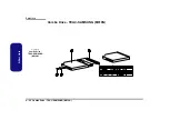
Страница 53: ...Part Lists A 6 CD ROM Drive QSI M300N A Part Lists CD ROM Drive QSI M300N Figure 4 CD ROM Drive QSI M300N ...
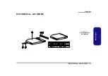
Страница 55: ...Part Lists A 8 CD RW Drive KME M300N A Part Lists CD RW Drive KME M300N Figure 6 CD RW Drive KME M300N ...
Страница 56: ...Part Lists CD RW Drive TEAC M300N A 9 A Part Lists CD RW Drive TEAC M300N Figure 7 CD RW Drive TEAC M300N ...
Страница 57: ...Part Lists A 10 Combo Drive QSI M300N A Part Lists Combo Drive QSI M300N Figure 8 Combo Drive QSI M300N ...
Страница 59: ...Part Lists A 12 DVD ROM Drive QSI M300N A Part Lists DVD ROM Drive QSI M300N Figure 10 DVD ROM Drive QSI M300N ...
Страница 61: ...Part Lists A 14 Top M310N A Part Lists Top M310N Figure 12 Top M310N ...
Страница 62: ...Part Lists Bottom M310N A 15 A Part Lists Bottom M310N Figure 13 Bottom M310N ...
Страница 63: ...Part Lists A 16 LCD M310N A Part Lists LCD M310N Figure 14 LCD M310N ...
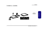
Страница 64: ...Part Lists CD ROM Drive QSI M310N A 17 A Part Lists CD ROM Drive QSI M310N Figure 15 CD ROM Drive QSI M310N ...
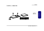
Страница 66: ...Part Lists CD RW Drive KME M310N A 19 A Part Lists CD RW Drive KME M310N Figure 17 CD RW Drive KME M310N ...
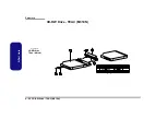
Страница 67: ...Part Lists A 20 CD RW Drive TEAC M310N A Part Lists CD RW Drive TEAC M310N Figure 18 CD RW Drive TEAC M310N ...
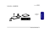
Страница 68: ...Part Lists Combo Drive QSI M310N A 21 A Part Lists Combo Drive QSI M310N Figure 19 Combo Drive QSI M310N ...
Страница 70: ...Part Lists DVD ROM Drive QSI M310N A 23 A Part Lists DVD ROM Drive QSI M310N Figure 21 DVD ROM Drive QSI M310N ...


