


4
(3) Clamp the lever down until the point where a click
can be felt. (Fig. 5)
Fig. 5
NOTE:
The motor housing can be temporarily secured by
clamping the lever (the motor housing does not slide
down by its own weight).
If the motor housing slides down, make adjustments
by tightening the knob nut.
Turning the knob nut clockwise tightens the lever,
while turning the knob nut counterclockwise loosens
the lever.
(4) While holding up the base slightly, turn the motor
housing clockwise until the index line on the motor
housing reaches the desired depth indicated on the
scale ring. (Fig. 4)
(5) Close the lever firmly.
2. Guiding the router
(1) Template Guide:
Use the template guide when employing a template
for producing a large quantity of identically shaped
products.
As shown in Fig. 6, secure the template guide to the
base of the router with two accessory screws. At this
time, ensure that the projection side of the template
guide is facing the bottom surface of the base of the
router.
Fig. 6
A template is a profiling mold made of plywood or
thin lumber. When making a template, pay particular
attention to the matters cescribed blow and illustrated
in Fig. 7.
When using the router along the interior plane of the
template, the dimensions of the finished product will
be less than the dimensions of the template by an
amount equal to dimension “A”, the difference
between the radius of the template guide and the
radius of the bit. The reverse is frue when using the
router along the exterior of the template.
Knob nut
Lever
Template
guide
Screw
Fig. 7
Secure the template to the workpiece. Feed the router
in the manner that the template guide moves along
the template as shown in Fig. 8.
Fig. 8
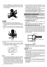
(2) Straight guide
Use straight guide for chamfering and groove cutting
along the materials side.
1
Insert the guide bar into the hole in the bar holder,
then lightly tighten the 2 wing bolts (A) on top of the
bar holder.
2
Insert the guide bar into the hole in the base, then
firmly tighten the 2 hex socket bolts (standard
accessories).
3
Make minute adjustments of the dimensions between
the bit and the guide surface with the feed screw, then
firmly tighten the 2 wing bolts (A) on top of the bar
holder and the wing bolt (B) that secures the straight
guide. (Fig. 9)
Fig. 9
Bit
Template
guide
Template
A
Template
Guide bar
Feed screw
Hex
socket
bolt
Guide
plane
Straight
guide
Bar
holder
Wing
bolt (A)
Wing
bolt (B)
Содержание M 12SC
Страница 9: ...8 ...
Страница 10: ...9 ...
Страница 11: ...10 ...
Страница 12: ...701 Code No C99133011 Printed in China Hitachi Koki Co Ltd ...


