background image

4

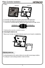
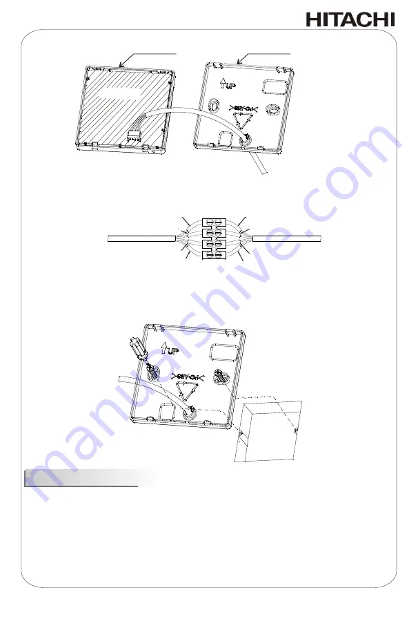
Wiring

A

.

Connect the controlling cable with upper cover terminal as the figure above.

B

.

Connect the other attached controlling cable with indoor unit control board

.

C

.

Connect the 2 controlling cables with attached connecting terminal as the figure


below:

 Controlling cable 

YL

YL

BL

BL

RD

RD

BK

BK

 Controlling cable 

Firmly fasten the connection cord after connection.

Circuit board of 

wired controller

upper cover

lower cover

GN

D

RX

D

TXD

+12V

GN

D

RX

D

TXD

+12V

5

.

Securing


the lower cover.

Please secure the lower cover with the attached screws (2 pcs) on the wall or embedded box.

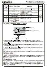
Custom parameters

The internal parameters of the wired controller can be set with the actual usage conditions. 
The catalogue of custom

-

setting parameters is shown as follows:

Wired


Controller Installation

Содержание HCWA21NEWH

Страница 1: ...HCWA21NEWH Installation and Operation Manual HPU2017003HA HITACHI WIRED CONTROLLER Model INSTALLATION AND OPERATION MANUAL ...

Страница 2: ...roduction 8 Wired Controller 8 LCD Screen 9 Basic Operation 10 Function Set 11 Super mode 11 Mute mode 11 Sleep mode 11 Button Lock 12 Filter Clean Reset 12 Clock Set 12 Single Timer ON OFF 13 Daily ON OFF Timer 13 Weekly Timer 14 Maintenance Troubleshooting and After Sale Service 15 ...

Страница 3: ...hen installing the wired controller Please contact your local agent as the occasion arises Installation and maintenance should be performed by a qualified personnel If you have any questions contact your distributor or dealer This manual should be considered as a permanent part of the air conditioning equipment and should remain with it Immediate hazards which WILL result in severe personal injury...

Страница 4: ...hock or electronic parts failure may occur Do not install the appliance or connect the wires before reading the manual Usage of spray such as pesticides paint hair gel or other toxic gases within 1 meter of the appliance is prohibited If the ELB Electric Leakage Break or fuse trouble is liable to occur please consult local service provider Do NOT place any object on the unit that is not related to...

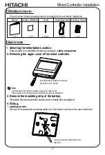
Страница 5: ...g scratched during removal and installation 1 Selecting the Installation Location 2 Removing the upper cover of the wired controller Insert the slotted screwdriver in the slots and press on it for removal 4 Wiring 3 Remove the insulating strip of the battery Leading out wire Pull one of the attached controlling cable out of the lower cover from the rear round hole Otherwise the wired controller ca...

Страница 6: ...RD BK BK Controlling cable Firmly fasten the connection cord after connection Circuit board of wired controller upper cover lower cover G ND RXD TXD 12V G ND RXD TXD 12V 5 Securing the lower cover Please secure the lower cover with the attached screws 2 pcs on the wall or embedded box Custom parameters The internal parameters of the wired controller can be set with the actual usage conditions The ...

Страница 7: ...stom setting mode and the screen will display the self setting parameter code and icon Press the button to select the custom setting parameter code and function code will also be displayed on the LCD Press the up button or minus button to select the function code and press ON OFF button to confirm the setting 1 2 3 The wired controller room temperature display and limit set temperature can be revi...

Страница 8: ... quit Press the button to exit without settings 2 Room temperature correction Room temperature correction Setting room temperature correction is for particular cases e g remote located at an area with different temperature than the room wired controller is set to display room temperature but the room temperature detected is different from the actual room temperature so setting correction is necess...

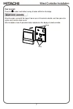
Страница 9: ...splay Align the upper cover with the hasp of lower cover of the wired controller and then press the upper cover onto the lower cover After installation tear off protective sticker attached on the display of wired controller Upper cover assembly Hasp Hasp Wired Controller Installation 7 ...
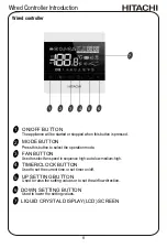
Страница 10: ... current time or set timer on off The appliance will be started or stopped when this button is pressed Press this button to select the operation mode UP SETTING BUTTON DOWN SETTING BUTTON Used to raise the setting values or to set the airflow direction Used to lower the setting values 5 LIQUID CRYSTAL DISPLAY LCD SCREEN 7 8 1 2 3 4 5 6 Wired Controller Introduction ...

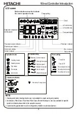
Страница 11: ...Operation mode Temperature display Fan speed setting Timer setting Timer ON Timer OFF Timer setting valid only once Timersettingvalidonlyforoneday Timer setting set for a week Room temperature Set temperature flickering Cooling mode Auto fan speed Ultrahigh fan speed High fan speed Medium fan speed Low fan speed Ultralow fan speed Heating mode Dry mode Fan mode Auto mode Fan speed display Clock Pa...

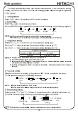
Страница 12: ...ING HEATING AUTO FAN ONLY DRY AUTO mode is invalid for models without AUTO mode when setting HEATING mode is invalid for cooling only types or heating forbidden air conditioners 1 Turning ON OFF Press the button the appliance will be started or stopped 2 Mode setting Press button to select operation mode Each time MODE button is pressed the operation mode will change in the following sequence 5 Ai...

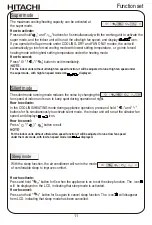
Страница 13: ...ction it will be adjusted to run at low fan speed under the mute mode with low fan speed mode icon displayed Super mode Silent mode The silent mode running mode reduces the noise by changing the fan speed of indoor unit so as to keep quiet during operation at night How to activate In the COOLING HEATING mode during appliance operation press and hold and buttons for 5s simultaneously to activate si...

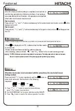
Страница 14: ...tton lock function has been set Button lock How to activate Press and hold and buttons simultaneously for 5s to activate button lock function and icon will be displayed on the LCD How to cancel Press and hold and buttons simultaneously for 5s again to unlock and icon will disappear from the LCD FILTER CLEAN screen prompt is only available for some models For details please refer to indoor unit man...

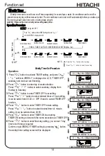
Страница 15: ...lay will return to previous screen and icon will appear on the upper right corner of the screen How to cancel To cancel TIMER ON press button to activate the timer on setting press button to adjust time hour until icon OFF appears press button to confirm cancellation and exit You can set Single TIMER OFF with the same method when the appliance is ON Operation Press button to activate TIMER set and...

Страница 16: ...n to activate TIMER setting and press until icon WEEKLY is displayed on LCD TIMER OFF weekday and clock set are flickering Press button to enter day of week selection Press button to select weekday display from Sunday to Saturday Press button to enter TIMER OFF hour setting Press button to select desired timer of hour setting it can be select from 00 23 or OFF if need to cancel TIMER OFF function ...

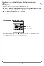
Страница 17: ...neutral detergent diluted with water squeeze the cloth tightly and clean the surface Wipe the surface with a dry cloth Do not use any thinner organic solvents or strong acid Troubleshooting and After sales Service When the air conditioner malfunctions will be displayed on the LCD indicating that error is occurring please consult your local dealer or after sales service Error code Error indicator ...

Страница 18: ...ditioning Inc Hitachi Johnson Controls Air Conditioning Inc Specifications in this document are subject to change without notice in order that Hitachi Johnson Controls Air Conditioning Inc may bring the latest innovations to their customers ...

Отзывы: