ENGLISH
6
HAS-K252
2
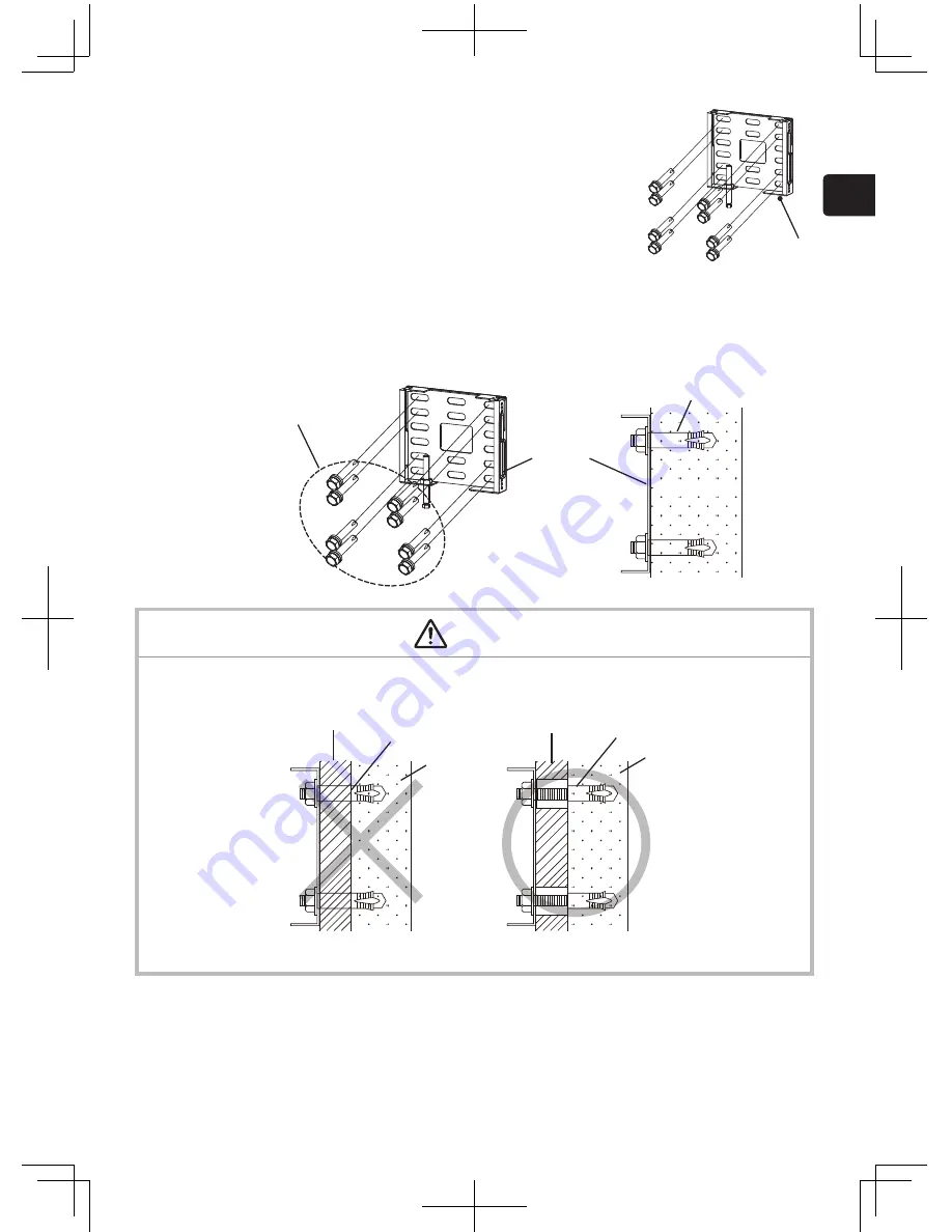
Remove the base bracket (O) from the arm assembly (A).
Before attaching the arm assembly to a wall, remove the screws to disassemble it as shown in the figure below.
Before disassembly, place the arm assembly on a mat or the protective plastic it was shipped in to prevent
damaging the floor or the bracket.
* Part names in the figures on the following pages are indicated by the symbols given in the ( ) brackets.
Note:
The groove in the base bracket (O) is engaged with the tab at the rear of the arm (M). Move the base bracket
away from the arm and then downward to remove it.
(L) M5 shoulder screws (3)
(M) Arm
(O) Base bracket
(L)
(L)
(L) (P)
(P)
(P)
(N)
M5 screw with spring
washer and flat washer
(M) Arm
Tab (rear of arm)
(O) Base bracket
Tab
7
HAS-K252
3
Attach the base bracket (O) to a wall using the anchor
bolts (M10).
The holes in the base bracket (O) are oval to permit horizontal adjustment.
For details on the length and number of the anchor bolts (M10) that are required,
see “Tools needed for installation” on page 2.
(O)
■
Use anchor bolts to attach the base bracket (O) to a wall.
■
Use M10 anchor bolts.
■
Use anchor bolts of a length that suits the material, strength and thickness of the wall so that the pullout strength of
each bolt meets or exceeds 2,000 N.
■
If the bolts cannot satisfy the required strength specifications, increase the number bolts.
M10 anchor bolts
(8 or more)
Base bracket (O)
Anchor bolt
Concrete
WARNING
■
When attaching the wall mount unit to a wall covered with a layer of plaster or other weak finishing material, make
sure the anchor bolts reach into the underlying concrete.
■
As shown in the figure, at least eight anchor bolts, two in each corner are required.
Concrete
Concrete
Weak material
Weak material
Anchor bolt
Anchor bolt


