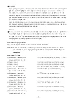
--- 20 ---
9-1-2. Reassembly
Reassembly can be accomplished by following the disassembly procedure in reverse. However, special attention
should be given to the following items.
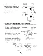
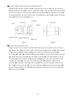
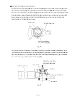
Mounting hammer holder (A)
Set the Retainer Sleeve
[16]
, O-ring (S-34)
[14]
,
Damper (A)
[17]
and Hammer Holder (A)
[18]
in the
Front Cover
[12]
. Supporting the flange portion of the
Front Cover
[12]
with a proper jig, lightly push in Ring
(B)
[20]
using a proper jig of 44 mm outside dia. and
a hand press. At this time, check that Ring (B)
[20]
is
fitted in the groove of the Front Cover
[12]
securely
(Fig. 18).
Ring (B)
Hammer holder (A)
O-ring
Retainer sleeve
Fig. 18
Damper (A)
Front cover
Proper jig
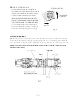
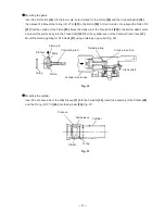
Mounting the first gear and the crank shaft
Mount the O-ring (S-40)
[44]
to the Cylinder Crank Case
[47]
. Press-fit the Ball Bearing 6203DDCMPS2L
[45]
and mount the Retaining Ring for D40 Hole
[43]
using a retaining ring puller. Press-fit the Crank Shaft
[42]
in
the Ball Bearing 6203DDCMPS2L
[45]
and mount the Oil Seal
[46]
. Put one Feather Key 4 x 4 x 10
[38]
in the
groove of the Crank Shaft
[42]
. Supporting the flat portion of the Crank Shaft
[42]
with a proper steel bar,
press-fit the First Gear
[60]
with a proper jig. Before press-fitting, check that the key groove of the Feather Key
4 x 4 x 10
[38]
is aligned with the key groove of the First Gear
[60]
(Fig. 19).
Fig. 19
Cylinder crank case
First gear
Feather key
Oil seal
O-ring
Ball bearing
Retaining ring for D40 hole
Steel bar
Suitable tool
Crank shaft
Содержание H45MRY
Страница 36: ......

