12
(2) Ma k in g a nd br eak in g capa cit ies
Th e con t a ct or is defin ed by it s m a k in g a n d br ea k in g ca pa cit ies in a ccor da n ce wit h u t iliza t ion ca t egor ies specified in
Ta ble 5.
Th e t est s con cer n in g t h e ver ifica t ion of t h e m a k in g an d br ea k in g ca pa cit ies of t h e con t a ct or a r e in t en ded t o ver ify
t h a t t h e con t a ct or is ca pa ble of m a k in g a n d br ea k in g t h e cu r r en t s st a t ed in Ta ble 9, a n d n ot t o ver ify t h e con t a ct
wear over lon g per iods of opera t ion.
Th e verifica t ion s of m ak in g capa cit y a nd br eak in g capa cit y a r e m a de
a s separ a t e t est s.
1 . Ma kin g ca pacit y
Th e n um ber is 100:50 oper a t ions
of wh ich ar e m ade a t 85% an d 50 oper a t ions at 110% of t h e r at ed coil volt a ge.
2. Br eak in g ca pa cit y
Th e tot a l n um ber of open in g oper a t ion s to be m a de is 25.
Du r in g t ests wit h in t h e lim it s of specified m a k in g a n d br ea k in g capa cit ies a n d wit h t h e specified n u m ber of oper a-
t ions, t h er e sh a ll be n o per m a n ent ar cin g, n o fla shover between poles , n o blowin g of t h e fuse in t h e ear t h circu it a nd
n o weldin g of t he con t acts.
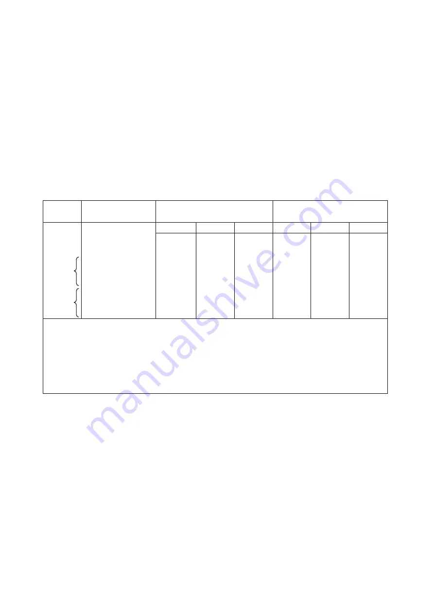
Ta ble 9. Con dit ion s for m ak in g a n d br eak in g corr espon ding t o t h e severa l ut iliza t ion ca t egor ies (IE C 60947-4-1)
Ca t egor y
Va lu e of t h e r at ed
oper at iona l cu rr en t
Mak e
Br ea k
I/Ie
U /Ue
cos
φ
(1)
Ic/Ie
U r /U e
cos
φ
(1)
AC-1
AC-2
AC-3
AC-4
(All valu es)
(All valu es)
Ie
≦
17A
17 A < Ie
≦
100 A
Ie > 100 A
Ie
≦
17A
17 A < Ie
≦
100 A
Ie > 100 A
1.5
4
10
10
8 (2)
12
12
10 (4)
1.1
1.1
1.1
1.1
1.1
1.1
1.1
1.1
0.95
0.65
0.65
0.35
0.35
0.65
0.35
0.35
1.5
4
8
8
6 (3)
10
10
8 (2)
1.1
1.1
1.1
1.1
1.1
1.1
1.1
1.1
0.95
0.65
0.65
0.35
0.35
0.65
0.35
0.35
Ie; Rat ed oper at iona l cu r ren t
U; Volt a ge befor e m ak e
U e; Ra ted oper at ion a l volt a ge
U r; Recover y volt a ge
I; Cu rr en t m a de
Ic; Cur r ent br ok en .
1) Toler an ce for cos
φ
:
±
0.05
2) Wit h a m inim um of 1000 A for I or Ic.
3) Wit h a m inim um of 800 A for Ic.
4) Wit h a m inim um of 1200 A for I.
(3) Mech an ica l endu r an ce
Wit h r espect t o it s r esist a n ce t o m ech a n ica l wea r, t h e cont a ct or is ch a r act er ized by t he n um ber of n o-load oper a t in g
cycles (i.e., wit h ou t cu r r en t on t h e m a in con t a ct s) wh ich ca n be m a de befor e it becom es n ecess a r y t o s er vice of
r eplace a n y m ech a n ica l pa rt s.
Th e con t a ct or sh a ll be inst a lled as for n orm a l ser vice; in pa r t icu la r, t h e condu ct or s sh a ll be con n ected in t he s a m e
m a n n er as for norm a l u se.
Th e coils of t h e con t r ol elect r o-m a gn et s sh a ll be su pplied a t t h eir r a t ed volt a ge a n d, if a pplica ble, a t t h eir r a t ed
fr equen cy.
Содержание H100C
Страница 2: ......
Страница 9: ...5 Fig 1 H35 Horizontal Plunger type Fig 2 H300C Link structure ...
Страница 36: ...32 Fig 28 ...
Страница 54: ......
Страница 55: ...Hitachi Industrial Equipment Systems Co Ltd ...


