background image

English

6

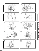
(1) Remove the 4mm screw, shown in 

Fig. 4

, with the

accessory hexagonal bar wrench, and remove the
guide roller from the main body.

(2) To reassemble the main body and the base, insert

the base locker between the base and the 4mm screw,
as shown in 

Fig. 4

, and securely clamp the 4mm

screw.

CHIP COVER POSITIONING

1. Chip cover

Use the chip cover to reduce flying of cut particles
and to easily operate the saw.
Slide the chip cover while lightly pressing its front
section.
The chip cover can be set at three positions as shown
in 

Fig. 5

.

2. How to choose the position of the ship cover

Set the chip cover to the first step when attaching or
removing the blade.
Set the chip cover to the second step when cutting
wooden materials.
Set the chip cover to the second or third step when
cutting metal materials such as steel.

CAUTION

Keep always the chip cover in the low position when
operating the tool.

Wear protection glasses even if the chip cover is
used.

ADJUSTING THE BLADE OPERATING
SPEED .......................................... (FCJ55VA only)

NOTE

The blade operating speed cannot be adjusted for
FCJ55.

The blade operating speed can be adjusted within a
range of 0 to 3,000/min according to the degree that the
trigger switch is depressed. Select the speed appropriate
to the material being worked and/or the working
conditions.
To achieve continuous operation, pull the trigger switch
all the way back and depress the stopper. Then, turn the
speed adjustment knob to adjust the blade operating
speed as desired.

NOTE

The speed adjustment knob rotates approximately 3
turns. To turn the switch OFF, pull the trigger switch
again to disengage the stopper, and release the trigger
switch.

CUTTING

CAUTION

While sawing, the base must be firmly in contact with
the material surface, and the blade must be held at a
right angle. If the base becomes separated from the
material, it could cause the blade to break.

When cutting while holding the front surface, be
careful of the moving blade and hold the upper part
firmly.

1. Rectilinear cutting

(1) To ensure accurate rectilinear cutting, employ the

optional accessory guide as shown in 

Fig. 6

.

(2) Use the splinter guard to reduce roughness of the

cutting surface of wooden materials. Attach the
splinter guard by inserting it from the front section of
the base until it clicks into place. (

Fig. 7

)

CAUTION

Set the base in the front position when using the
splinter guard.

2. Cutting a circle or a circular arc

To ensure efficient cutting, employ the optional
accessory guide and nail or wood screw as shown in

Fig. 8

.

When mounting the guide, loosen the base bottom
screw, and shift the base as far forward as it will go.

3. Sawing curved lines

When sawing a small circular arc, reduce the feeding
speed of the machine. If the machine is fed too fast, it
could cause the blade to break.

4. Cutting metallic materials

Always use an appropriate cutting agent (spindle oil,
soapy water, etc.). When a liquid cutting agent is not
available, apply grease to the back surface of the
material to be cut.

5. Pocket cutting

(1) In lumber

Aligning the blade direction with the grain of the
wood, cut step by step until a window hole is cut in
the center of the lumber. (

Fig. 9

)

(2) In other materials

When cutting a window hole in materials other than
lumber, initially bore a hole with a drill or similar tool
from which to start cutting.

6. Angular cutting

Set the chip cover to the first step. (

Fig. 5

)

To adjust the angle of inclination; loosen the base
bottom screw, shift the base position to the side
groove of the semicircular portion, align the scale on
the base semicircular portion (figures engraved on
the scale indicate the angle of inclination) with the
housing edge line, and thoroughly tighten the base
bottom screw. (

Fig. 10

 and 

11

)

CAUTION

Set the screw to the opposite side of the inclining
side when using the guide. (

Fig. 12

)

SELECTION OF BLADES

1. Accessory blades

To ensure maximum operating efficiency and results
it is very important to select the appropriate blade
best suited to the type and thickness of the material
to be cut. One type of blade is provided as standard
accessory. The blade number is engraved in the
vicinity of the mounting portion of each blade. Select
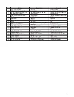
appropriate blades by referring to 

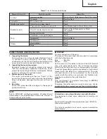
Table 1

.

2. Acceptable commercial blades (Fig. 13)

This machine is designed to accept most blades
available on the open market. As illustrated in

Fig. 13

, blade dimension restrictions are as follows:

Thickness : L2 ..... Less than 1.6mm

Width

: L3 ..... 6.3mm

L4 ..... 8mm
L5 ..... 7mm

NOTE

When cutting thick materials, use HITACHI genuine blades
which have an inclination as shown in 

Fig. 3-A

 or 

B

.

Содержание FCJ 55

Страница 1: ... Lire soigneusement et bien assimiler ces instructions avant usage Prima dell uso leggere attentamente e comprendera queste istruzioni Deze gebruiksaanwijzing s v p voor gebruik zorgvuldig doorlezen Leer cuidadosamente y comprender estas instrucciones antes del uso Handlinginstructions Bedienungsanleitung Moded emploi Istruzioni per l uso Gebruiksaanwijzing Instrucciones de manejo FCJ 55VA FCJ 55 ...

Страница 2: ...del FCJ55 refer to the drawing and the list FCJ55VA FCJ55VA Item No Part Name 1 Chip Cover 2 Housing A B Set 3 Tube D 4 Switch 5 Tube D 6 Earth Terminal 7 Noise Suppressor 8 Connector 50091 9 Tapping Screw W Flange D4 20 10 Name Plate 11 HITACHI Label 12 Carbon Brush 13 Brush Holder 14 Cord Armor 15 Cord 16 Cord Clip 17 Tapping Screw W Flange D4 16 18 Plate Nut 19 Hex Socket Hd Bolt M4 8 20 Base 2...

Страница 3: ...1 2 1 2 4 1 2 5 2 5 9 0 4 3 0 6 8 9 7 6 5 A 1 2 3 B C 8 7 8 D B C E 10 9 3 11 13 1 2 3 4 5 6 7 8 9 0 A B C D E F G H I ...

Страница 4: ...ogement Base Sägetisch Base Base locker Sicherungsvorrichtung für den Section de blocage de la base Sägetisch 4mm screw 16mm 4mm Schraube 16mm Vis de 4mm 16mm Chip cover Schnipseldeckel Couvercle d éclats Guide Führungsrolle Guide 4mm screw 8mm 4mm Schraube 8mm Vis de 4mm 8mm Splinter guard Splitterschutz Anti éclats Nail or wood screw Nagel oder Holzschraube Clou ou vis de bois Scale Skala Echell...

Страница 5: ...ase Zaagtafel Base Bloccaggio della base Veiligheidsinrichting voor de Gaveta de base zaagtafel Vite da 4mm 16mm 4mm schroef 16mm Tornillo 4mm 16mm Reccoglitrucioli Spaankast Cubierta de virutas Guida Geleider Guía Vite da 4mm 8mm 4mm schroef 8mm Tornillo 4mm 8mm Para schegge Anti splinterstuk Protector contra astillas Chiodo o vite del legno Spijker of houtschroef Clavo o tornillo para madera Sca...

Страница 6: ...d the work It is safer than using your hand and it frees both hands to operate tool 13 Do not overreach Keep proper footing and balance at all times 14 Maintain tools with care Keep cutting tools sharp and clean for better and safer performance Follow instructions for lubrication and changing accessories Inspect tool cords periodically and if damaged have it repaired by authorized service center I...

Страница 7: ...sion cord should be kept as short as practicable MOUNTING THE BLADE 1 Use the accessory hexagonal bar wrench to loosen the blade set screws on the set ring as shown in Fig 1 2 Holding the blade with its cutting edge facing the front insert the mounting portion of the blade into the plunger groove until it touches the bottom of the groove 3 As shown in Fig 1 firmly clamp the side screw CAUTION 䡬 Lo...

Страница 8: ...materials Attach the splinter guard by inserting it from the front section of the base until it clicks into place Fig 7 CAUTION Set the base in the front position when using the splinter guard 2 Cutting a circle or a circular arc To ensure efficient cutting employ the optional accessory guide and nail or wood screw as shown in Fig 8 When mounting the guide loosen the base bottom screw and shift th...

Страница 9: ...ool Exercise due care to ensure the winding does not become damaged and or wet with oil or water 4 Servicing Consult an authorized Service Agent in the event of power tool failure NOTE Due to HITACHI s continuing program of research and development the specifications herein are subject to change without prior notice IMPORTANT Correct connection of the plug The wires of the main lead are coloured i...

Страница 10: ...rausreißen Das Kabel sollte gegen Hitze Öl und scharfe Kanten geschützt werden 12 Den Arbeitsplatz gut absichern Zwingen oder einen Schraubstock zur Befestigung des Werkstücks verwenden Das ist sicherer als die Benutzung der Hände und macht beide Hände zur Bedienung des Werkzeugs frei 13 Sich niemals weit überbeugen Immer einen festen Stand und ein sicheres Gleichgewicht bewahren 14 Die Werkzeuge ...

Страница 11: ...chenden Querschnitts und ausreichender Nennleistung zu verwenden Das Verlängerungskabel sollte so kurz wie möglich gehalten werden ANBRINGEN DES SÄGEBLATTS 1 Mit dem Sechskantinnenschlüssel werden die Klemmschrauben des Sägeblatts am Einstellring gelöst Abb 1 2 Das Sägeblatt mit der Schnittseite nach vorn halten und den Befestigungsteil des Sägeblatts bis zum Anschlag in den Schlitz der Schwingspu...

Страница 12: ... dann wird der Drückerschalter losgelassen SCHNEIDEN ACHTUNG 䡬 Beim Sägen muß der Sägetisch fest auf der Oberfläche des Werkstücks auf liegen und das Sägeblatt im rechten Winkel gehalten werden Wenn der Sägetisch das Material nicht berührt kann das zum zerbrechen des Sägeblatts führn 䡬 Wenn Sie beim Schneiden die Vorderseite halten auf das sich auf und abbewegende Sägeblatt achten und das Oberteil...

Страница 13: ...Platte oder Nr 6 Dünnen Platte Geschäumtes Styrol usw Nr 2 Holzfasermaterial Pappe Wellpappe Nr 2 Hartfaserplatte Nr 5 oder Nr 6 Faserplatte Nr 6 Sonstige Hartgummi Nr 2 Schiefer Nr 5 WARTUNG UND INSPEKTION 1 Inspektion des Sägeblattes Die Weiterverwendung eines stumpfen oder beschädigten Sägeblattes führt zu verminderter Schnittleistung und kann eine Überbelastung des Motors hervorrufen Das Sägeb...

Страница 14: ... 12 Fixer fermement la piêce à travailler Utiliser des agrafes ou un étau pour la maintenir C est plus sûr que d utiliser ses mains et cela les libêre pour faire fonctionner l outil 13 Ne pas présumer de ses forces Essayer de garder son équilibre en toute circonstance 14 Entretenir les outils avec soin Les conserver bien aiguisés et les nettoyer afin d en obtenir les meilleures performances et de ...

Страница 15: ...fil de rallonge d une épaisseur suffisante et d une capacité nominale suffisante Le fil de rallonge doit être aussi court que possible MONTAGE DE LA LAME 1 Utiliser la clef à six pans pour desserrer les vis de réglage de la lame sur la bague de réglage suivant la Fig 1 2 En tenant la lame avec son bord de coupe vers l avant introduire la section de montage de la lame dans la fente du piston jusqu ...

Страница 16: ...n maintenant la surface avant rester attentif au mouvement de la lame et maintenir fermement la partie supérieure 1 Coupe rectiligne 1 Pour obtenir une coupe rectiligne précise employer le guide accessoire en option comme montré à la Fig 6 2 Utiliser le guide anti éclats pour réduire l irrégularité de la coupe des matériaux en bois Fixer le guide en l insérant par l avant sur la base jusqu au décl...

Страница 17: ... provoquer une surcharge du moteur Remplacer la lame par une nouvelle dès que des traces d abrasion apparaissent 2 Contrôle des vis de montage Vérifier régulièrement les vis de montage et s assurer qu elles sont correctement serrées Resserrer immédiatement toute vis desserrée Sinon il y a danger sérieux 3 Entretien du moteur Le bobinage de l ensemble moteur est le coeur même de l outil électro por...

Страница 18: ...oggetti fermi Fissare saldamente l oggetto in una morsa Èpiù sicuro che non tenendolo fermo con le mani che restano libere per maneggiare l elettroutensile 13 Non squilibrare il corpo durante l esecuzione di un lavoro Stare sempre su due piedi in equilibrio stabile 14 Trattare gli utensili elettrici con cura Tenerli sempre puliti ed affilati per un funzionamento migliore e più sicuro Seguire le is...

Страница 19: ...pessore e di prestazione adeguata La prolunga deve essere più Corta possibile MONTAGGIO DELLA LAMA 1 Usare la chiave maschia esagonale fornita come accessorio per allentare le viti di fissaggio della lama sull anello di fissaggio così come indicato nella Fig 1 2 Tenendo la lama con il taglio verso l avanti inserire nel solco del pistone la parte della lama destinata al fissaggio fino a che quest u...

Страница 20: ...e bene a contatto con la superficie dell oggetto de lavorare e la lama deve essere tenuta ad angolo retto Se la base si destacca dal materiale si può verificare la rottura della lama 䡬 Durante operazioni di taglio eseguite impugnando la superficie anteriore fare attenzione alla lama in movimento e tenere saldamente la parte superiore 1 Taglio rettilineo 1 Per ottenere un taglio rettilineo accurato...

Страница 21: ...ica ecc n 2 o n 4 piastra spessa o n 6 piastra sottile Schiuma stirolica ecc n 2 Pasta Cartone cartone ondulato n 2 Fibra di legno n 5 o n 6 Legno sintetico n 6 Altri Gomma dura n 2 Ardesia n 5 MANUTENZIONE E CONTROLLO 1 Controllo della lama L uso continuativo di lame danneggiate o rovinate comporta una ridotta efficacia nel taglio e può causare sovraccarico del motore Sostituire la lama con una n...

Страница 22: ...rpe hoeken 12 Neem de uiterste veiligheid in acht Gebruik klemmen of een bankschroef om het werkstuk vast te zetten Hierdoor heeft u uw handen vrij om het gereedschap te bedienen 13 Buig u nooit te ver naar voren Kies een goede plaats en behoud altijd uw evenwicht 14 Behandel het gereedschap voorzichtig Zorg ervoor dat het gereedschap scherp en schoon is zodat een goed en veilig prestatievermogen ...

Страница 23: ...at voldoende dwarsprofiel en voldoende nominaal vermogen heeft Het verlengsnoer moet zo kort mogelijk gehouden worden HET AANBRENGEN VAN HET ZAAGBLAD 1 Met de inbussleutel worden de klemschroeven van het zaagblad aan instelring losgedraaid zoals afgebeeld in Afb 1 2 Het zaagblad wordt met de snijkant naar voren in de gleuf van de stoter geschoven tot het de bodem van de groef raakt 3 Volgens Afb 1...

Страница 24: ...aagtafel het materiaal niet aanraakt kan dat tot een breuk van het zaagblad leiden 䡬 Als u bij het zagen de voorkant vasthoudt dient u goed op te letten voor het bewegende zaagblad en het bovengedeelte stevig vast te houden 1 Zagen met een parallelgeleider 1 Gebruik voor precies rechtlijnig zagen de parallelgeleider los verkrijgbaar zoals te zien is in Afb 6 2 Het anti splinterstuk vermindert de r...

Страница 25: ... 4 dikke plaat of nr 6 dunne plaat Geschuimd styrol etc nr 2 Houtvezelmateriaal Karton golfkarton nr 2 Hardboard nr 5 of nr 6 Vezelplaat nr 6 Overig materiaal Eboniet nr 2 Steen nr 5 ONDERHOUD EN INSPECTIE 1 Inspectie van de zaagbladen Het verder gebruiken van stompe of beschadigde zaagbladen leidt tot een verminderde zaagmoet worden prestatie en kan een overbelasting van de motor veroorzaken Het ...

Страница 26: ...ue usar las manos ademas ambas manos quedan libres para operar la herramienta 13 No extenderse excesivamente para efectuar un trabajo Mantener en todo momento un buen balance y base de apoyo 14 Mantener cuidadosamente las herramientas Tener las siempre limpias y afiladas para obtener un mejor rendimiento y un funcionamiento más seguro Seguir siempre las instrucciones para la lubricación y el cambi...

Страница 27: ...posición ON conectado las herramientas eléctricas empezarán a funcionar inesperadamente provocando un serio accidente 3 Cable de prolongación Cuando el área de trabajo está alejada de la red de acometida usar un cable de prolongación suficiente grueso y potente El cable de prolongación debe ser mantenido lo más corto posible MONTAR LA CUCHILLA 1 Usar la llave macho haxagonal accesoria para soltar ...

Страница 28: ... de ajuste de velocidad se deja girar aproximadamente 3 vueltas Para girar el conmutador en OFF desconectado volver a apretar el pulsador de nuevo para desacoplar el dispositivo de ajuste y soltar el pulsador CORTE PRECAUCION 䡬 Durante el serrado la base tiene que entrar firmemente en contacto con la superficie de la pieza de trabajo y la cuchilla tiene que ser mantenida al ángulo correcto Si se s...

Страница 29: ...gada Clorulo de vinilo resina acrílica etc No 2 o No 4 chapa gruesa o No 6 chapa delgada Estirol espumoso etc No 2 Pasta de papel Cartón cartón ondulado No 2 Fibra prensada dura No 5 o No 6 Fibra prensada No 6 Otros Goma dura No 2 Pizarra No 5 MANTENIMIENTO E INSPECCION 1 Inspección de la cuchilla El uso continuo de una cuchilla dañada resultaría una deficiencia de corte reducido y podría causar u...

Страница 30: ...ormas o con los documentos de normalización EN50144 EN55014 y EN61000 3 según indican las Directrices del Consejo 73 23 CEE 89 336 CEE y 98 37 CE Esta declaración se aplica a los productos con marcas de la CE English EC DECLARATION OF CONFORMITY We declare under our sole responsibility that this product is in conformity with standards or standardized documents EN50144 EN55014 and EN61000 3 in acco...

Отзывы: