Product Specifications and Operating Instructions
3-4
13
C
hoosing a Connection
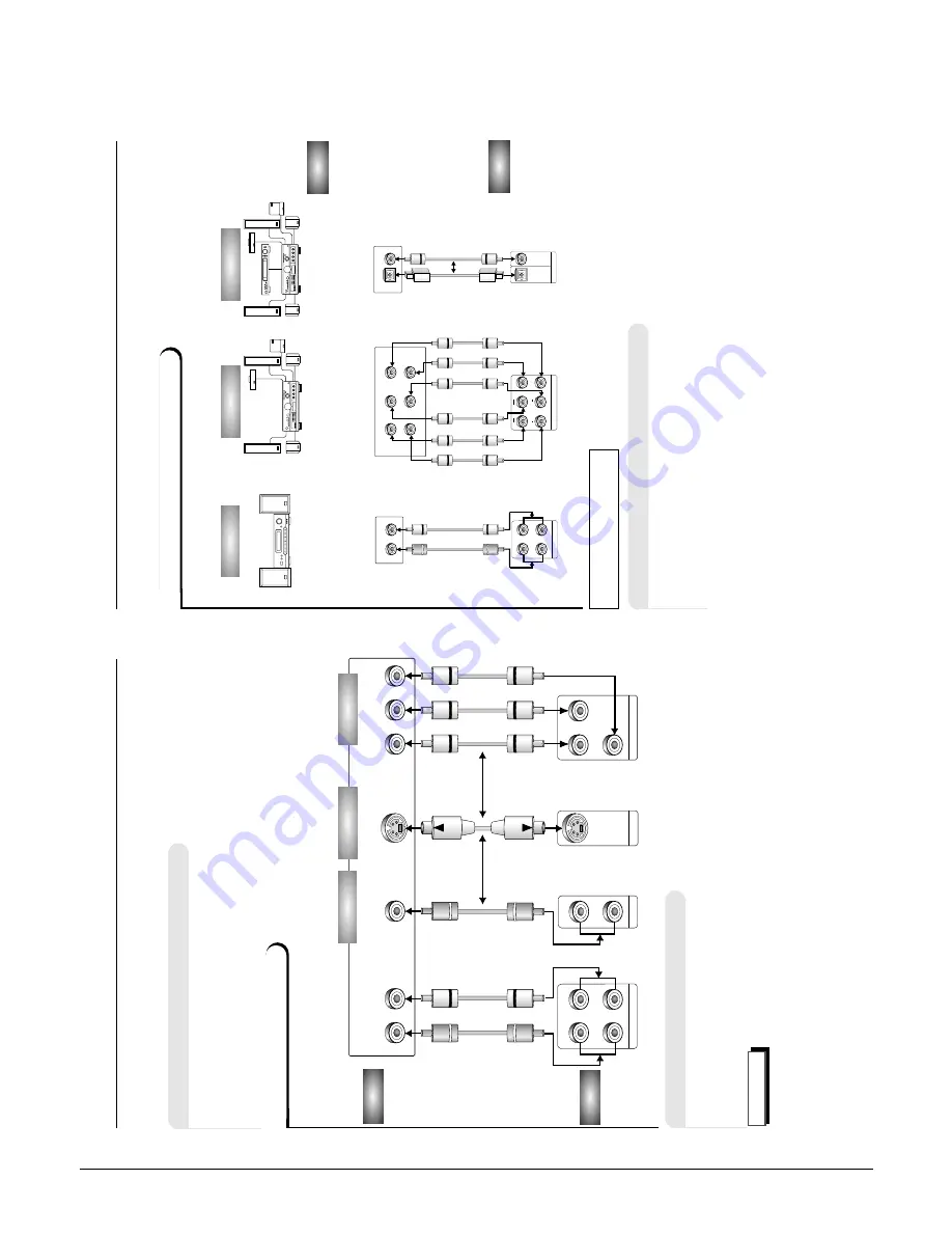
Connection to an
Audio System
Connection to an
Audio System
Mixed Audio
Out
5.1
ch Analog Amplifier
Audio Input Jacks
2ch Amplifier
Dolby Pro Logic Decoder
Audio Input Jacks
Analog Audio
Out
AUDIO
DVD
•
Method 1
DVD 2ch Stereo
Amplifier or Dolby Pro Logic Decoder
•
Method 2
DVD
Amplifier with 5.1ch
Analog Input Jacks
•
Method 3
DVD
Amplifier with Dolby Digital Decoder/DTS Deco
der
Method 1
Method 2
Dolby Digital Decoder
DTS Decoder
Digital
Audio Input Jack
Digital Audio
Out
Method 3
MIXED A
U
DIO OUT
R1
R2
L1
RL
L2
ANALOG A
U
DIO OUT
R
R
FR
ONT
SURR
OUND
L
C
ENTER
F
ront (RH)
F
ront (LH)
LS
W
Center
Rear (RH)
Rear (LH)
Subw
oof
e
r
OPTICAL
C
O
AXIAL
OPTICAL
C
O
AXIAL
DIGIT
A
L A
U
DIO OUT
OR
Output signal of L1 and L2 is same.
Output signal of R1 and R2 is same.
RL
Y
Pr
Pb
COMPONENT VIDEO
OUT
Y
Pr
Pb
MIXED A
UDIO OUT
VIDEO OUT
S-VIDEO OUT
R2
L2
V2
V1
R1
L1
12
C
hoosing a Connection
Connection to a TV
•
Method 1
DVD
TV with V
ideo Input Jack
•
Method 2
DVD
TV with S-V
ideo Input Jack
•
Method 3
DVD
TV with Component V
ideo Input Jacks
TV (Normal, Widescreen, Projection, etc..)
Connection to a TV (For V
ideo)
Basic Audio
V
ideo Input Jack
OR
OR
A
V
Cable
(included)
S-V
ideo
Cable
(not included)
V
ideo
Cables
(not included)
Good picture
Better picture
Best picture
DVD
TV
Method 1
Method 2
Method 3
Audio Input
Jacks
S-V
ideo input Jack
Component V
ideo input Jacks
The following show examples of connections commonly used to connect
the DVD player with a
TV and other components.
•
Always turn of
f the DVD player
,
TV
, and other components before you connect
or disconnect any cables.
•
Refer to owner's manual of the components you are connecting for more
information on those particular components.
Before Connection the DVD Player
NOTE
•
If the VIDEO OUT
SELECT
SWITCH (on the rear panel) is set to "Y
, Pb, Pr", the "S-
V
ideo" may not work.
•
If the VIDEO OUT
SELECT
SWITCH is set to "S-V
ideo", the "Y
, Pb, Pr" may not work.
•
After correcting the switch, turn power of
f and then on again.
Содержание DVC-605U
Страница 59: ...4 24 Disassembly and Reaasembly MEMO ...
Страница 79: ...Circuit Descriptions 5 20 MEMO ...
Страница 91: ...Troubleshooting 6 12 MEMO ...
Страница 92: ...7 1 7 Exploded View 7 1 Cabinet Assembly 7 2 Deck Assembly Page 7 2 7 3 ...
Страница 94: ...Exploded Views 7 3 7 2 Deck Assembly 107 906 108 TS16391 ...
Страница 95: ...Exploded Views 7 4 MEMO ...
Страница 97: ...8 2 Replacement Parts List MEMO ...
Страница 99: ...Block Diagram 9 2 MEMO ...
Страница 101: ...PCB Diagrams 10 2 10 1 S M P S ...
Страница 102: ...PCB Diagrams 10 3 10 2 Main COMPONENT SIDE SOLDER SIDE ...
Страница 103: ...PCB Diagrams 10 4 10 3 Jack ...
Страница 104: ...PCB Diagrams 10 5 10 4 Front COMPONENT SIDE SOLDER SIDE ...
Страница 105: ...PCB Diagrams 10 6 10 5 Key COMPONENT SIDE SOLDER SIDE ...
Страница 106: ...PCB Diagrams 10 7 10 6 Deck 10 8 Sensor 10 7 Motor 10 9 Switch ...
Страница 107: ...PCB Diagrams 10 8 MEMO ...
Страница 108: ...11 1 11 Wiring Diagram ...
Страница 109: ...Wiring Diagram 11 2 MEMO ...
Страница 111: ...Schematic Diagrams 12 2 12 1 S M P S ...
Страница 112: ...Schematic Diagrams 12 3 12 2 Main Micom ...
Страница 113: ...Schematic Diagrams 12 4 12 3 Servo ...
Страница 114: ...Schematic Diagrams 12 5 12 4 RF ...
Страница 115: ...Schematic Diagrams 12 6 12 5 Data Processor ...
Страница 116: ...Schematic Diagrams 12 7 12 6 AV Decoder ...
Страница 117: ...Schematic Diagrams 12 8 12 7 Video ...
Страница 118: ...Schematic Diagrams 12 9 12 8 Audio ...
Страница 119: ...Schematic Diagrams 12 10 12 9 Audio 5 1 Channel ...
Страница 120: ...Schematic Diagrams 12 11 12 10 AV Interface ...
Страница 121: ...Schematic Diagrams 12 12 12 11 Front Micom ...
Страница 122: ...Schematic Diagrams 12 13 12 12 Key ...
Страница 123: ...Schematic Diagrams 12 14 12 13 Deck ...
Страница 124: ...Schematic Diagrams 12 15 12 14 Motor Switch Sensor ...
Страница 125: ...Schematic Diagrams 12 16 12 15 Remote Control ...


