-27-
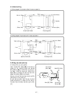
4. Internal wiring
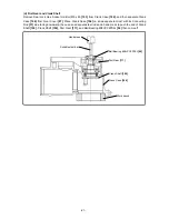
(1) Wiring diagram for products without a noise suppressor
(2) Wiring diagram for products with a noise suppressor
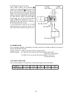
5. Wiring around switches
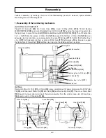
(1) Wiring of the reversing switch
Insert Internal Wire (Blue)
[45]
to terminal (1)
marked on the reversing switch and Internal
Wire (Brown)
[46]
to terminal (2) as shown in
the figure. Insert the lead wire (White) from
Stator
[73]
to terminal (3) and the lead wire
(Black) from Stator
[73]
to terminal (4).
Gently pull on each inserted lead wire to confirm
that the wires do not come out.
For wire disconnection, insert the tip of a small
slotted screwdriver or needle into the hole on
the side of each terminal, and then pull out the
wire.
Cord
Stator
Stator
Armature
Speed control switch
Reversing switch
Black or Brown
White or Blue
Gray
White
Lead wire (Brown)
Lead wire (Blue)
Black
Red
Noise suppressor
Cord
Stator
Stator
Armature
Speed control switch
Reversing switch
Black or Brown
White or Blue
Gray
White
Lead wire (Brown)
Lead wire (Blue)
Black
Red
Internal Wire
(Brown)
[46]
Stator
[73]
: Black
Internal Wire
(Blue)
[45]
Stator
[73]
: White

