background image

5b

5b

5c

5c

5d

5d

6

6

K

5a

5a

S

S

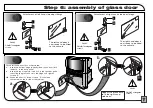
Step 5: securing the speaker to the console

At the back of the console, under the top shelf, insert a dowel ‘K’,
as illustrated. This is to prevent the speaker box from being 
inserted too far into the console at the next stage.

Slide the speaker box into the console,
between the dowels on the shelf.

Check that the speaker box
locates correctly with the dowel
that was inserted at step 5a.

From underneath, secure
the speaker to the 
supporting shelf with 2
screws ‘S’.

The TV console unit is now
ready for the attachment of
the glass doors.

Содержание CST258PC

Страница 1: ...M00016 CST258PC CST258PS CST32APC CST32APS CST32BPW SERVICE MANUAL CAUTION Before servicing this chassis it is important that the service technician read the Safety Precautions and Product Safety Notices in this service manual Data contained within this Service manual is subject to alteration for improvement ...

Страница 2: ...ASSEMBLY SUPPLEMENT The following pages are extracted from the Customer Assembly Guide to assist Service Engineers ...

Страница 3: ... 0 1 2 3 0 0 1 4 5 06 7 8 0 9 1 ...

Страница 4: ...R S AUDIO LINE IN AUDIO LINE IN SURROUND OUTPUT INPUT C L DC 18V 200mA 2 x 6 W 16 Speaker Console Assembly Guide CST32APC PS ...

Страница 5: ...dealer Do not place water filled vessels on top of your TV s cabinet Do not remove any fixed cover as this may expose dangerous voltages Do not leave equipment switched on when it is unattended unless it is specifically stated that it is designed for unattended operation or has a standby mode Switch off using the switch on the equipment and make sure that your family know how to do this Special ar...

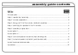
Страница 6: ...preparation 4 Step 4 fixing your TV to the console 5 Step 5 securing the speaker to the console 6 Step 6 assembly of glass door 7 Sound option 1 8 Sound option 2 9 Step 7 surround speaker connection free standing unit 10 Step 8 surround speaker connection wall mounted unit 11 Sound mode and technical data 12 Guarantee 13 title ...

Страница 7: ...X4 X2 X2 X2 X2 X9 B C G F E D H I J K L M N O Q T S X8 R X2 P 1 1 U console parts NOTE For the construction of this console you will also require a Phillips screwdriver not supplied If any parts are missing please consult your dealer immediately ...

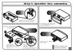
Страница 8: ...w T and adjust the screw so that the head is flush with the centre of I a Insert bushes C into the speaker grille b Push fit the speaker grille onto the front of the speaker box assembly Speaker box is now prepared for later stages DO NOT connect plug to mains at this stage ensure that plug socket is secure to speaker Step 1 speaker box assembly a Insert screws T The screw heads are to be used to ...

Страница 9: ...ole Insert the metal cam fixings F into the slotted side of the side panels Use a screw driver to insert dowel D into the the pillar Repeat this step to the other pillar Ensure that the long slot of the of the cam fixing F is pointing towards the hole on the edge of the side panel Fit the pillar to the assembled side pillar and side panel as illustrated Turn the cam fixing F clockwise to lock the ...

Страница 10: ...de the back panel into place b IMPORTANT Before fixing the top panel in place make sure that it is facing the correct way up The side with large recessed holes must be on the underside Once you are sure that the top panel is fitted correctly use 4 screws G to fix the top panel to the side panels as illustrated Use the allen key U to tighten the screws c Fit both components I in place IMPORTANT The...

Страница 11: ... in the side panels 2 per side b Insert 4 dowels K into the speaker shelf and place the shelf into the cabinet you may have to tilt the shelf at an angle to allow it to pass through the front pillars Rest the shelf on the dowels in the side panels a Secure the shelf to the side panels with screws G Use the allen key U to tighten the screws b Insert 2 bushes C into the base panel as illustrated Ste...

Страница 12: ...speaker box from being inserted too far into the console at the next stage Slide the speaker box into the console between the dowels on the shelf Check that the speaker box locates correctly with the dowel that was inserted at step 5a From underneath secure the speaker to the supporting shelf with 2 screws S The TV console unit is now ready for the attachment of the glass doors ...

Страница 13: ...first as illustrated a Insert the bottom hinge already fixed to the door into the bush in the base panel b Insert the top hinge into the bush in the speaker grille then slide the glass door into the hinge and tighten screws R NB When the door in closed screws R should be concealed on the inside of the cabinet Repeat this procedure to fit the right hand side door The left hand door is now ready to ...

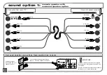
Страница 14: ...rom rear of TV to rear of speaker console Surround speaker connections from speaker box console Surround speakers As supplied with your speaker console 2 ONLY use surround speakers with impedance as stated on your console speaker box 1 THESE connectors must only be connected to the sockets on the speaker box and NOT the TV s sockets IMPORTANT For connection of leads to speakers see page 10 Surroun...

Страница 15: ...om rear of TV to rear of speaker console black plug green plug blue plug red plug white plug black plug blue plug red plug white plug green plug Connect infra red leads to TV S socket and output socket of speaker box Infra red signal sent to speakers for output of sound refer to instructions supplied with infra red unit Rear view of TV and console Magnified view of model C32WD2TN Magnified view of...

Страница 16: ...ors grey with black stripe into black connector plain grey into red connector 1 10 10 black red plain grey grey with black stripe Step 7 surround speaker connection free standing unit Remove connector cover from speaker housing to expose connection switches Replace connector cover after lead connection is complete Speaker connection lead ...

Страница 17: ...m the speaker housing to expose the connector sockets Connect the leads as shown on the previous page then secure the connection cover to an interior wall as illustrated Place speaker housing back onto secured connector cover Speaker and sound direction can now be angled for individual needs ...

Страница 18: ...through Surround External Speaker Impedance 2 x 16 Surround 12 12 W x D x H sound mode technical data When all the equipment is connected it is recommended that the Normal Speaker Set Up mode is selected in order to achieve the best possible audio performance For more information regarding the various speaker modes refer to Speaker Set Up in the main Users Guide ...

Страница 19: ...The product has not been repaired maintained or modified by any person other than an Hitachi authorised engineer iii The product serial number has not been removed or altered This Guarantee does not apply to product aquired secondhand or for commercial or communal use Any parts replaced under this Guarantee shall become the property of Hitachi Home Electronics Europe Ltd Please note that evidence ...

Страница 20: ...RANCE RADIO TV ELETRO MENAGER S A 4 Allee des Sorbiers Parc d activite du Chene BP 45 69671 Bron cedex FRANCE Tel 33 04 72 14 29 70 HITACHI SALES IBERICA S A Gran Via Carlos Tercero 101 1 1 Barcelona 08028 ESPAÑA Tel 34 93 330 86 52 HITACHI HOME ELECTRONICS HELAS S A 91 Falirou St117 41 Athens GREECE Tel 01 924 2620 HITACHI HOME ELECTRONICS NORDIC AB Haukadalsgatan 10 Box 77 164 94 Kista SVERIGA T...

Страница 21: ...R S AUDIO LINE IN AUDIO LINE IN SURROUND OUTPUT INPUT C L DC 18V 200mA 2 x 6 W 16 Speaker Console Assembly Guide CST258PC PS ...

Страница 22: ...dealer Do not place water filled vessels on top of your TV s cabinet Do not remove any fixed cover as this may expose dangerous voltages Do not leave equipment switched on when it is unattended unless it is specifically stated that it is designed for unattended operation or has a standby mode Switch off using the switch on the equipment and make sure that your family know how to do this Special ar...

Страница 23: ...g your TV to the console and bush assembly 4 Step 4 securing your speaker to the TV console 5 Step 5 assembly of glass door 6 Sound option 1 7 Sound option 2 8 Step 6 surround speaker connection free standing unit 9 Step 7 surround speaker connection wall mounted unit 10 Sound mode and technical data 11 Guarantee 12 title ...

Страница 24: ... X1 X1 X1 X1 X20 X1 X1 X1 A X2 X2 X2 X9 B C D E F G H I J K L N P Q X4 O X1 M 1 1 console parts NOTE For this console construction you will also require a Phillips screwdriver not supplied if any parts are missing please consult your dealer ...

Страница 25: ...distance of 4mm is required from the rear face of the speaker to the head of the screw to aid with measure ment place component F along side screw P adjust the screw so head is flush with the centre of F a Insert bush C into speaker grille b Place speaker grille onto front of speaker box assembly Speaker box is now prepared for later stages DO NOT connect plug to mains at this stage ensure that pl...

Страница 26: ... 2a 2a step 2 console preparation Construct the base and side supports of the console using the allen key to secure screws D Console is now prepared for next stage Ensure side panels and pillars are positioned as seen in the illustration ...

Страница 27: ...f in preparation of securing with screws D b Insert 4 more of the dowels H into the speaker shelf and place the shelf into the cabinet you may have to tilt the shelf at an angle to allow it to pass through the front pillars resting on the inserted dowels To complete this stage secure shelf to side panels with screws D using the allen key to tighten then insert door bush on the console base ready f...

Страница 28: ...the top shelf insert a dowel H this is to prevent you inserting your speaker box too far into the console at the next stage Slide in the speaker box onto the shelf until it is aligned with the dowels placed in Step 3c Rear View Your speaker box should now sit correctly on the shelf From underneath secure your speaker to the supporting shelf with two screws Q The TV console unit is now ready to hav...

Страница 29: ...J O K L O I 5a 5a 5b 5b 5c 5c K L N M 6 6 step 5 assembly of glass door DO NOT overtighten screws DO NOT overtighten screws GLASS Glass door is now ready for insertion into console ...

Страница 30: ... from rear of TV to rear of speaker console Surround speaker connections from speaker box console Surround speakers supplied with your speaker console 2 ONLY use surround speakers with impedance as stated on your console speaker box 1 THESE connectors must only be con nected to the sockets on the speaker box and NOT the TV s sockets IMPORTANT For connection of leads to speakers see page 9 Surround...

Страница 31: ...om rear of TV to rear of speaker console black plug green blue plug red plug white plug black plug blue plug red plug white plug green Connect infra red leads to TV S socket and output socket of speaker box Infra red signal sent to speak ers for output of sound refer to instructions supplied with infra red unit rear view of TV and console rear view magnifiction of C2886TN and C28WD2TN models rear ...

Страница 32: ...tors grey with black stripe into black connector plain grey into red connector 1 9 9 black red plain grey grey with black stripe step 6 surround speaker connection free standing unit Remove connector cover from speaker housing to expose connection switches Replace connector cover after lead connection is complete Speaker connection lead ...

Страница 33: ... cover from speaker housing as shown to expose connector sockets and connect leads as shown on previous page then secure connection cover to interior wall Place speaker housing back onto secured connector cover Speaker and sound direction can now be angled for individual needs ...

Страница 34: ...2 W through Centre 2 x 6 W through Surround External Speaker Impedance 2 x 16 Surround For best audio performance when all equipment is connected it is recommended that you choose Normal mode from Speaker Set Up For more information about various speaker modes refer to Speaker Set Up in your main Users Guide 11 11 sound mode technical data ...

Страница 35: ...The product has not been repaired maintained or modified by any person other than an Hitachi authorised engineer iii The product serial number has not been removed or altered This Guarantee does not apply to product aquired secondhand or for commercial or communal use Any parts replaced under this Guarantee shall become the property of Hitachi Home Electronics Europe Ltd Please note that evidence ...

Страница 36: ...RANCE RADIO TV ELETRO MENAGER S A 4 Allee des Sorbiers Parc d activite du Chene BP 45 69671 Bron cedex FRANCE Tel 33 04 72 14 29 70 HITACHI SALES IBERICA S A Gran Via Carlos Tercero 101 1 1 Barcelona 08028 ESPAÑA Tel 34 93 330 86 52 HITACHI HOME ELECTRONICS HELAS S A 91 Falirou St117 41 Athens GREECE Tel 01 924 2620 HITACHI HOME ELECTRONICS NORDIC AB Haukadalsgatan 10 Box 77 164 94 Kista SVERIGA T...

Страница 37: ...n 3 of IC10 this voltage is compared with an internal reference voltage of approximately 0 8V should the applied voltage exceed the reference the pulse width is limited from output pin 6 chip in over current mode In this way Q4 is offered protection from changes in primary current Secondary overvoltage protection is offered also by R77 should the feedback be disabled then the secondary voltage wil...

Страница 38: ......

Страница 39: ......

Страница 40: ......

Страница 41: ......

Страница 42: ......

Страница 43: ......

Страница 44: ......

Страница 45: ......

Страница 46: ......

Страница 47: ......

Страница 48: ......

Страница 49: ......

Страница 50: ......

Страница 51: ......

Страница 52: ......

Страница 53: ......

Страница 54: ......

Страница 55: ......

Страница 56: ......

Страница 57: ......

Страница 58: ...THE UPDATED PARTS LIST FOR THIS MODEL IS AVAILABLE ON ESTA ...

Страница 59: ... ITALY Tel 39 02 487861 Tel 39 02 38073415 Servizio Clienti Fax 39 02 48786381 2 Email customerservice italy hitachi eu com HITACHI Europe AB Box 77 S 164 94 Kista SWEDEN Tel 46 0 8 562 711 00 Fax 46 0 8 562 711 13 Email csgswe hitachi eu com HITACHI EUROPE S A S Lyon Office B P 45 69671 BRON CEDEX FRANCE Tel 04 72 14 29 70 Fax 04 72 14 29 99 Email france consommateur hitachi eu com HITACHI EUROPE...

Отзывы: