

-13-
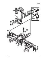
Main Pipe Comp.
[170] <170>
Level Mark
[169]<169>
Loop Handle Ass’y Anti-vib.
[161]<161>
Handle Bracket (A)
[173]<173>
Bolts 6 x 43/P (Black)
[174]<174>
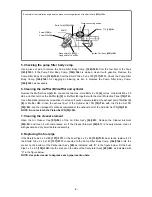
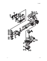
Piston Set
PN
[55]<54>
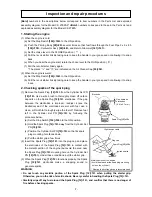
Exhaust mark (arrow)
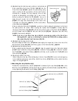
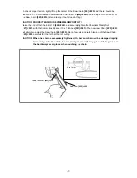
(3) Reassembling the crank case ass’y, piston set, and cylinder set
When press-fitting the Oil Seal TB12227
[63]<62>
into the
Crank Case Ass'y
[61]<60>
, position the pressurizing spring
inside, and then fill the gap between the lips with Pyronoc
Universal No. 0 (Nippon Oil Corp.). Dispose of the oil seal
removed at disassembly, and always use a new oil seal.
Before mounting the Cylinder Set PN
[19]<19>
, be sure to
apply two-cycle engine oil to the Ball Bearing 6001 C3
[64]<63>
, the large and small bearings at the ends of the
connecting rod, Piston Ring
[56]<55>
, and the outer surface
of the Piston Set PN
[55]<54>
.
When mounting the Piston Set PN
[55]<54>
, position it so that the exhaust mark (arrow) on the top of
the piston points to the muffler. When mounting the Cylinder Set PN
[19]<19>
, correctly align the
closed gap of the Piston Ring
[56]<55>
with the lock pin at the groove in the Piston Set PN
[55]<54>
,
and the Cylinder Set PN
[19]<19>
with the Piston Set PN
[55]<54>
. Otherwise, the Piston Ring
[56]<55>
may be easily damaged.
NOTE: If you use a new Crank Case Ass'y [61]<60>, unnecessary portion of the Crank Case
Packing [62]<61> must be cut off along the Cylinder Set PN [19]<19> matching surface
after assembling the Crank Case Ass'y [61]<60>.
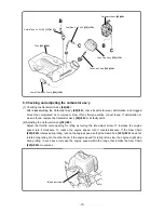
(4) Reassembling the magneto rotor comp.
Mount the Magneto Rotor Comp.
[136]<136>
while aligning the integral key at the center hole of the
Magneto Rotor Comp.
[136]<136>
with the key groove in the Crank Shaft Ass’y
[60]<59>
.
(5) Reassembling the carburetor ass'y
When reassembling the Carburetor Ass'y
[48]<48>
, align the pulsed holes on the Carburetor Gasket
[47]<47>
and Throttle Wire Fixing Plate
[46]<46>
, Carburetor Packing
[45]<45>
, Carburetor Insulator
Set PN
[43]<43>
, and Intake Packing
[42]<42>
with those on the Cylinder Set PN
[19]<19>
and
Carburetor Ass'y
[48]<48>
.
(6) Mounting the clutch drum comp.
While holding the inner ring of the ball bearing in the Fan Case
[118]<118>
so as not to damage two
4-mm cylindrical protrusions, press-fit the Clutch Drum Comp.
[119]<119>
and then attach the Stop
Ring C-12 Outer
[117]<117>
.
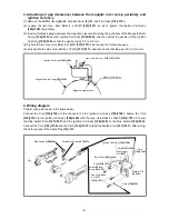
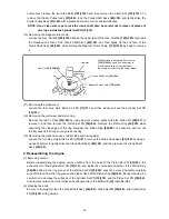
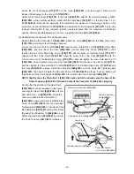
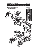
3. Mounting the loop handle ass’y
Position the Loop Handle Ass’y Anti-vib.
[161]<161>
as indicated by the Level Mark
[169]<169>
on the
Main Pipe Comp.
[170]<170>
, and then fasten the loop handle with Handle Bracket (A)
[173]<173>
by
evenly tightening the two Bolts 6 x 43/P (Black)
[174]<174>
.


