8
28
Fig. 16
NOTE
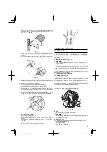
When you have lost the proper position of the screw (28), start
with the most counterclockwise position.
Starting
CAUTION
Before starting, make sure the cutting attachment does not
touch anything.
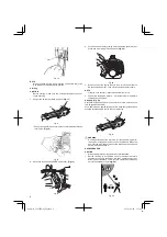
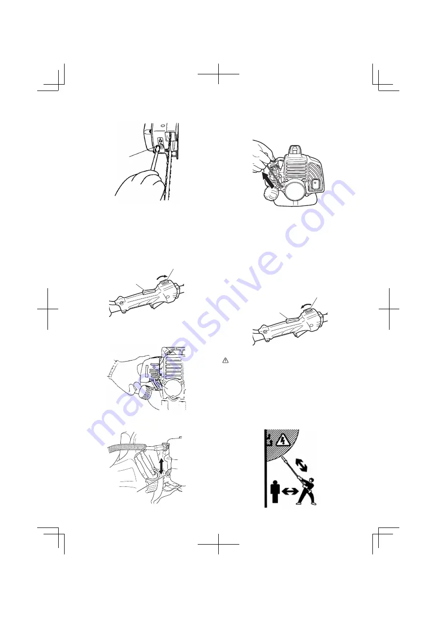
1. Set ignition switch (29) to ON position. (
Fig. 17
)
29
30
Fig. 17
* Push priming bulb (31) several times so that fuel
fl
ows through
return pipe. (
Fig. 18
)
31
Fig. 18
2. Set choke lever (51) to CLOSED position (A). (
Fig. 19
)
51
Fig. 19
3. Pull recoil starter briskly, taking care to keep the handle in your
grasp and not allowing it to snap back. (
Fig. 20
)
Fig. 20
4. When you hear the engine want to start, return choke lever to
RUN position (open) (B). Then pull recoil starter briskly again.
NOTE
If engine does not start, repeat procedures from 2 to 5.
5. Then allow the engine about 2 – 3 minutes to warm up before
subjecting it to any load.
Stopping (Fig. 21)
Decrease engine speed and run at an idle for a few minutes, then
turn o
ff
ignition switch (29).
For models with an engine ignition switch, keep the ignition switch
pressed until the engine comes to a complete stop.
29
30
Fig. 21
WARNING
A cutting attachment can injure while it continues to spin after
the engine is stopped or power control is released. When the
unit is turned o
ff
, make sure the cutting attachment has stopped
before the unit is set down.
SAFE OPERATION
CAUTION
○
Always wear gloves during operation or maintenance.
○
Review the area to be trimmed. Look for hazards that could
contribute to unsafe conditions. DO NOT operate unit if any
wires (power, telephone, cable, etc.) are closer than 15M to any
part of the operator or unit. (
Fig. 22
)
15 m
Fig. 22
000Book̲CS27EPA(S)̲Eng.indb 8
000Book̲CS27EPA(S)̲Eng.indb 8
2014/06/04 15:14:27
2014/06/04 15:14:27

