background image

--- 8 ---

The following test data should be used for reference purposes only since the cutting speed and the working

capacity may vary depending on the operating conditions such as the pressing force, type of blades, materials,

etc.

Fig. 5

Содержание CR 24DV

Страница 1: ...POWER TOOLS TECHNICAL DATA AND SERVICE MANUAL CORDLESS SABER SAW CR 24DV SPECIFICATIONS AND PARTS ARE SUBJECT TO CHANGE FOR IMPROVEMENT LIST No F850 May 2001 C MODEL CR 24DV ...

Страница 2: ...VICE MANUAL a symbol s is are used in the place of company name s and model name s of our competitor s The symbol s utilized here is are as follows Symbols Utilized Competitors Company Name Model Name P DEWALT DW008 1645 USA GSA24VE EUROPE B BOSCH ...

Страница 3: ...Specification Comparisons 7 6 2 Working Performance per Single Charge reference only 7 7 PRECAUTIONS IN SALES PROMOTION 9 7 1 Safety Instructions 9 7 2 Inherent Drawbacks of Cordless Saber Saw Requiring Particular Attention during Sales Promotion 11 7 3 Front Cover 12 8 REPAIRE GUIDE 12 8 1 Precautions in Disassembly and Reassembly 12 9 STANDARD REPAIR TIME UNIT SCHEDULES 19 Assembly Diagram for C...

Страница 4: ...features the Hitachi original mechanism that enables one hand mounting and dismounting of saw blades same as the Model CR 13VA and the soft grip handle for ease of operation 3 APPLICATIONS Cutting metal wood plastics etc 4 SELLING POINTS Saw blade can be mounted and removed without the use of tools Saw blade can be mounted in either direction upward or downward Widely rubber covered case for comfo...

Страница 5: ...atically secured in a released state by turning it all the way In the released state the built in spring force pulls the holder pin back to the correct position automatically Thus saw blades can be smoothly replaced with one hand 1 2 2 Saw blade can be mounted in either direction upward or downward The Model CR 24DV is convenient for cutting materials on the floor or near window frames and also fo...

Страница 6: ...nd securely mounted to the motor by hooking the claw of the carbon brush on the connecting portion on the outside of the brush tube Fig 2 Fig 3 4 Lock off button The lock off button is adopted to avoid the switch from unintentionally being turned on during storage or carrying 5 Convenient switch trigger shape for easy operation The switch trigger is large enough to operate with two fingers for eas...

Страница 7: ...ominal life Charging discharging approximately 1 000 cycles in case of Model UC 24YFB Nominal capacity 2 0 Ah Battery Model EB 2430HA Sealed cylinder nickel metal hydride storage battery Nominal voltage DC 24V Nominal life Charging discharging approximately 500 cycles in case of Model UC 24YFB Nominal capacity 3 0 Ah Charger Model UC 24YFB Power source Single phase AC 50 60 Hz Voltage Depending on...

Страница 8: ...5 sec ON 0 5 sec OFF Stays ON constantly Storage battery or charger is faulty Charging not possible because storage battery temperature is too high Pilot lamp indications UC 24YFB Blade No Uses Thickness mm 2 5 6 3 32 1 4 No 1 No 3 No 96 No 95 No 9 No 8 No 5 No 4 No 2 2 5 6 3 32 1 4 50 70 2 2 3 4 2 5 6 3 32 1 4 Below 2 5 3 32 Below 2 5 3 32 Below 3 5 1 8 Below 30 1 3 16 Below 100 4 2 5 15 3 32 5 8...

Страница 9: ...3 8 in outer diameter No 107 For cutting steel and stainless pipes less than 100 mm 4 in outer diameter No 106 For cutting steel and stainless pipes less than 60 mm 2 3 8 in outer diameter No 105 For cutting and roughing lumber No 121 All purpose No 131 All purpose except for cutting steel and stainless pipes more than 30 mm 1 3 16 in outer diameter No 132 2 5 6 3 32 1 4 2 5 6 3 32 1 4 Below 3 5 1...

Страница 10: ... 7 6 COMPARISONS WITH SIMILAR PRODUCTS 6 1 Specification Comparisons 6 2 Working Performance per Single Charge reference only Fig 4 ...

Страница 11: ...ing test data should be used for reference purposes only since the cutting speed and the working capacity may vary depending on the operating conditions such as the pressing force type of blades materials etc Fig 5 ...

Страница 12: ...o overheat and burnt out 4 Do not use any voltage increasing equipment transformer etc between the power source and the charger If the charger is used with voltage over and above that indicated on the unit it will not function properly 5 Conduct battery charging at an ambient temperature range of 0 C 4 C 32 F 104 F Special temperature sensitive devices are employed in the charger to permit rapid c...

Страница 13: ...da For the U S A For Australia and New Zealand For Europe 9 Disposal of the Model EB 2420 or EB 2430HA storage battery Ensure that all customers understand that Model EB 2420 or EB 2430HA Storage Batteries should be returned to the Hitachi power tool sales outlet or authorized service center when they are no longer capable of being recharged or repaired If thrown into a fire the batteries may expl...

Страница 14: ...V is 2 0 Ah and 3 0 Ah the actual capacity may vary within 10 of that value depending on the ambient temperature during use and charging and the number of times the batteries have been recharged It should be noted that other factors which may have a bearing on the amount of work possible per charge are the working conditions ambient temperature type and moisture content of the workpiece sharpness ...

Страница 15: ...ne Screws W SP Washer M4 x 12 22 and the Cover Plate 23 and pull out the Front Cover 24 Remove the four Hex Socket Hd Bolts W SP Washer M5 x 16 19 from the Upper Cover Ass y 20 Pull the Upper Cover Ass y 20 straight and remove it 2 Removal of the Plunger 14 from the Upper Cover Ass y 20 Remove the two Seal Lock Hex Socket Flat Hd Bolts M5 x 12 33 from the Connector 38 If the Seal Lock Hex Socket F...

Страница 16: ... 6901ZZCMPS2L 27 8 Disassembly of the blade mounting section Remove the Retaining Ring E type for D14 Shaft 13 from the Plunger 14 with a flat blade screwdriver Be careful that the Retaining Ring E type for D14 Shaft 13 is always loaded by Spring A 9 Slide the Guide Washer 7 backward and remove the two Steel Balls D4 76 5 Move Holder Sleeve B 4 backward and align the notch of Holder Sleeve B 4 so ...

Страница 17: ...g Button 66 and the power supply ass y DC speed Control Switch 56 Brush Holder B 54 Brush Holder A 65 and Terminal Support 69 are mounted can be removed 10 Removal of the power supply ass y from the Housing 52 Disconnect the internal wire from the Housing 52 and pull out Brush Holder B 54 and Brush Holder A 65 backward 11 Disassembly of the Housing 52 Remove the two Hex Hd Tapping Screws D4 x 60 5...

Страница 18: ...Holder Sleeve A 3 and Holder Sleeve B 4 as shown in Fig 9 Insert the Holder Pin 1 into the hole and push it in Slide Holder Sleeve B 4 and Holder Sleeve C 6 forward and turn them about 90 clockwise viewing from A Insert the two Steel Balls D4 76 5 use the arrow marks shown in Figs 9 and 10 as the reference Insert the other end of the Plunger 14 into the Guide Washer 7 Dust Washer 8 Spring A 9 Wash...

Страница 19: ... the Upper Cover Ass y 20 to the Gear Cover Ass y 32 5 Align the notch of the Magnet 49 with the protrusion of the Housing 52 when mounting the Magnet 49 to the Housing 52 6 Do not pinch internal wires between the mating surfaces of the Handle A B Set 57 when mounting the Handle A B Set 57 to the Housing 52 7 Adhesives are applied to the following screws and bolts When reusing these screws and bol...

Страница 20: ... Washer D5 x 30 31 2 9 0 5 N m 30 5 kgf cm Machine Screw W Washers M3 x 12 68 0 4 to 0 6N m 4 to 6 kgf cm Machine Screw W SP Washer M4 x 12 22 1 8 0 4 N m 18 4 kgf cm Seal Lock Flat Hd Screw M4 x 12 25 1 8 0 4 N m 18 4 kgf cm Hex Socket Hd Bolt W SP Washer M5 x 16 19 8 8 1 0 N m 90 10 kgf cm Seal Lock Hex Socket Flat Hd Bolt M5 x 12 33 5 4 0 5 N m 55 5 kgf cm Nylock Hex Socket Flat Hd Bolt M6 x 16...

Страница 21: ... 18 8 1 3 Wiring diagram Be sure to perform wiring connections as indicated in Figs 11 12 13 and 14 Fig 14 Fig 13 Fig 12 Fig 11 ...

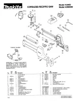
Страница 22: ...peed Control Switch Terminal Support Front Cover Armature Ass y Ball Bearing 608VV Ball Bearing 6001VV Gear Cover Ass y Spindle Ball Bearing 6901ZZ Gear Needle Bearing Connecting Piece A Connector Connector Holder Plunger Thrust Bearing Spring A O ring Upper Cover Ass y Seal Packing General Assembly Housing Magnet Base ...

Страница 23: ...ELECTRIC TOOL PARTS LIST LIST NO CORDLESS SABER SAW Model CR 24DV 2001 4 20 E1 F850 ...

Страница 24: ...1 24 319 867 FRONT COVER 1 25 993 244 SEAL LOCK FLAT HD SCREW M4X12 3 26 319 849 BEARING COVER B 1 27 690 1ZZ BALL BEARING 6901ZZCMPS2L 1 28 319 848 SPINDLE 1 29 954 789 METAL B 1 30 996 399 HEX SOCKET HD BOLT W FLANGE M5X12 1 31 986 011 TAPPING SCREW W SP WASHER D5X30 4 32 319 844 GEAR COVER ASS Y 1 INCLUD 29 33 319 875 SEAL LOCK HEX SOCKET FLAT HD BOLT M5X12 2 34 319 851 NYLOCK HEX SOCKET FLAT H...

Страница 25: ...9 305 490 TAPPING SCREW W FLANGE D4X30 BLACK 4 60 319 790 GRIP COVER 1 61 304 035 TAPPING SCREW W FLANGE D4X25 BLACK 2 62 HITACHI LABEL 1 63 319 847 BRUSH CAP 2 64 999 058 CARBON BRUSH 1 PAIR 2 65 319 813 BRUSH HOLDER A 1 66 319 865 PUSHING BUTTON 1 67 319 812 HEAT SINK 1 68 993 963 MACHINE SCREW W WASHERS M3X12 1 69 319 894 TERMINAL SUPPORT 1 70 319 805 BATTERY EB 2420 W ENGLISH N P 1 70 319 806 ...

Страница 26: ... 5 PCS 1 604 959 611 SABER SAW BLADES NO 4 5 PCS 1 605 958 185 SABER SAW BLADES NO 5 5 PCS 1 606 958 188 SABER SAW BLADES NO 8 5 PCS 1 607 996 427 SABER SAW BLADES NO 9 3 PCS 1 608 318 611 SABER SAW BLADES NO 101 150L P 10 5 PCS 1 609 318 612 SABER SAW BLADES NO 102 228L P 10 5 PCS 1 610 318 614 SABER SAW BLADES NO 104 228L P 14 5 PCS 1 611 318 615 SABER SAW BLADES NO 105 150L P 18 5 PCS 1 612 318...

Страница 27: ......

Отзывы: