15
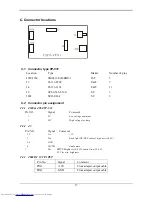
E-4 J2
Pin NO.
Signal
I/O Comment
1 GND
Ground
2
LI 2
Earphone out L
3
RI 2
Earphone out R
4
LI 1
Earphone out L
5
LO
Speaker out L
6 NC
No
connector
7
RI 1
Earphone out R
8
RO
Speaker out R
E-5 Switch definition
Location Definition
S1 Power
ON/OFF
S2
Function select by clockwise direction
S3
Function select by counter-clockwise direction
S4
Adjust up
S5 Adjust
down
E-6 LED definition
Location Definition
D1
Green for ON mode; Yellow for DC power off; stand by;
suspend and off mode.
E-7 Variable resistor
VR1:
Volume control , clockwise for decreasing ; counter-clockwis
for increasing
Содержание CML153
Страница 26: ...22 10 TROUBLESHOOTING A Main Procedure ...
Страница 27: ...23 A 1 Power Circuit Troubleshooting ...
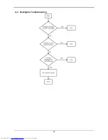
Страница 28: ...24 A 2 Backlights Troubleshooting ...
Страница 29: ...25 A 3 Performance Troubleshooting ...
Страница 30: ...26 A 4 Function Troubleshooting ...
Страница 31: ...27 APPENDIX A Display Unit Assembly ...
Страница 32: ...28 ...
Страница 33: ...29 APPENDIX B PCB ASSEMBLY ...
Страница 34: ...30 ...
Страница 35: ...31 ...
Страница 36: ...32 ...
Страница 37: ...33 ...
Страница 38: ...34 ...
Страница 39: ......
Страница 40: ...36 ...


