background image

English

14

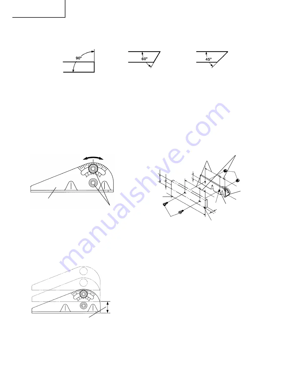
Fig. 8

Fig. 9

Flat hd. screw of more than
15/64" 

×

 19/32" (6 mm 

×

 15)

8-27/64"
(214 mm)

2-3/8" (60 mm)

1-5/64" (27.5 mm)

1-5/64" (27.5 mm)

4-23/32"
(120 mm)

1-49/64"
(45 mm)

15/64"
(6 mm) nut

Vise  (B)

Two holes 1/4"
(6.5 mm)

More than 15/64"

(6 mm)

Steel
board

M10 hexagon

socket head bolts

Vise (B)

4. Cutting at angles (Fig. 7 and 8).

The machine permits cutting at angles of 45° or 60°

Fig. 7

Loosen the two M10 hexagon socket head bolts on the vise (B), then set the working
surface on the vise-jaw at any angles of 0°, 30° or 45° as shown in Fig. 7.
Upon completion of setting, securely tighten the two M10 hexagon socket head bolts,
as shown in Fig. 8.

When wide material is to be cut at an angle, it should be firmly clamped by fixing a
steel board like Fig. 9 to the vise (B), as shown in Fig. 9.

5. Moving the stationary vise-jaw (Fig. 10).

The vise opening is set at the maximum of 6-11/16"
(170 mm) when shipped from the factory.
In case an opening more than 6-11/16" (170 mm)
is required, move the vise-jaw to the position
shown by the chain line, after unscrewing the two
bolts.
The maximum opening can be set in two steps
8-5/64" (205 mm) and 9-7/16" (240 mm).
When the material to be cut is excessively wide,
the vise can be effectively used by repositioning
the stationary side of the vise jaws.

Fig. 10

When setting at an
angle of 0°

When setting at an
angle of 30°

When setting at an
angle of 45°

The vise jaws open to 6-11/16"
(170 mm) while the vise can be
set in two steps 8-5/64" (205 mm)
and 9-7/16" (240 mm)

Содержание CC 14SE

Страница 1: ...ol can result in death or serious bodily injury This manual contains important information about product safety Please read and understand this manual BEFORE operating the power tool Please keep this manual available for other users and owners before they use the power tool This manual should be stored in safe place INSTRUCCIONES DE SEGURIDAD Y MANUAL DE INSTRUCCIONES ADVERTENCIA La utilización IN...

Страница 2: ...FONCTIONNEMENT PLUS SUR 23 NOM DES PIÈCES 25 SPÉCIFICATIONS 25 PRÉPARATION AVANT L UTILISATION 26 AUANT L UTILISATION 27 APPLICATIONS PRATIQUES 28 INSTALLATION ET RETRAIT DU DISQUE À TRONÇONNER 32 ENTRETIEN ET INSPECTION 33 SERVICE APRÀS VENTE ET RÉPARTIONS 34 ÍNDICE INFORMACIÓN IMPORTANTE SOBRE SEGURIDAD 35 SIGNIFICADO DE LAS PALABRAS DE SEÑALIZACIÓN 35 SEGURIDAD 36 PROLOGO 40 PIEZAS DE REPUESTO ...

Страница 3: ...ecautions are outlined in the SAFETY section of this Instruction Manual and in the sections which contain the operation and maintenance instructions Hazards that must be avoided to prevent bodily injury or machine damage are identified by WARNINGS on the power tool and in this Instruction Manual NEVER use this power tool in a manner that has not been specifically recommended by HITACHI MEANINGS OF...

Страница 4: ...OOLS Never force a tool or an attachment to do a job for which it was not designed 9 ALWAYS WEAR PROPER APPAREL WHEN WORKING WITH THE TOOL Never wear loose clothing gloves neckties rings bracelets or other jewelry which may get caught in the moving parts Always wear non slip footwear preferably with steel toes Wear protective hair covering to contain long hair 10 ALWAYS USE EYE PROTECTION WHEN WOR...

Страница 5: ...ious personal injury or damage to the tool Specific Safety Rules for Use of this Power Tool WARNING The following specific operating instructions must be observed when using this POWER TOOL to avoid injury DO s ALWAYS OBSERVE THE FOLLOWING RULES TO ASSURE SAFE USE OF THIS TOOL 1 Review this Manual and familiarize yourself with the safety rules and operating instructions for this POWER TOOL before ...

Страница 6: ...you have taken any medications or have consumed any alcoholic beverages 4 Never use the POWER TOOL for applications not specified in the Instruction Manual 5 Never operate the tool while wearing loose clothing a necktie or jewelry or while your hair is uncovered to protect against getting caught in the moving machinery 6 Never reach around or behind the cut off wheel 7 Never touch any moving parts...

Страница 7: ...ized outlet reverse the plug If it still does not fit contact a qualified electrician to install a polarized outlet Do not change the plug in any way DOUBLE INSULATION FOR SAFER OPERATION To ensure safer operation of this electric power tool HITACHI has adopted a double insulation system Double insulation as used here means a system of two insulations physically separated and arranged between elec...

Страница 8: ...English 8 SAVE THESE INSTRUCTIONS AND MAKE THEM AVAILABLE TO OTHER USERS AND OWNERS OF THIS TOOL ...

Страница 9: ...ions Thickness 7 64 2 8 mm wheel Hole Dia 1 25 4 mm Max working 16000 ft min 4800 m min peripheral speed No load speed 3700 min No load peripheral speed 13540 ft min 4125 m min Applicable workpiece materials Round bars pipes and various types of shaped steel 90 Max Height 4 17 32 115 mm Max Height 2 49 64 70 mm Max cutting Max Width 5 1 8 130 mm Max Width 9 1 4 235 mm dimensions 45 Max Height 4 11...

Страница 10: ...on cords for loose or exposed wires and damaged insulation before using Repair or replace as needed before using the power tool NOTE The lower the wire size number the heavier the wire and the farther it will carry current without a voltage drop WARNING Never connect this unit to an electrical power source until all operating instructions have been read and understood 3 Take off the chain As the m...

Страница 11: ...nts such as a cracked out off wheel is prevented by this safety cover wheel cover Although it has been fully clamped at the factory prior to delivery securely reclamp the mounting screws for safety Safety cover and wheel cover are designed to protect the operator from coming into contact with the cut off wheel during operation of the tool WARNING NEVER OPERATE THE POWER TOOL if the safety covers d...

Страница 12: ...inutes When starting routine work Over 1 minute 12 Inspect the rotating stability of the cut off wheel For precise cutting rotate the cut off wheel and check for deflection to confirm that the wheel is not noticeably unstable otherwise vibration might occur and cause an accident PRACTICAL APPLICATIONS WARNING Never remove or install a workpiece while the cut off wheel is rotating to avoide persona...

Страница 13: ...ther tightly it may be necessary to turn it to the left and right during mounting and removing 3 Cutting operation 1 Rotate the cut off wheel gently press down the handle and bring the cut off wheel close to the material to be cut 2 When the cut off wheel contacts the material gently press down the handle further and start cutting 3 When cutting or designated slotting is completed raise the handle...

Страница 14: ...material is to be cut at an angle it should be firmly clamped by fixing a steel board like Fig 9 to the vise B as shown in Fig 9 5 Moving the stationary vise jaw Fig 10 The vise opening is set at the maximum of 6 11 16 170 mm when shipped from the factory In case an opening more than 6 11 16 170 mm is required move the vise jaw to the position shown by the chain line after unscrewing the two bolts...

Страница 15: ...olt with a hex bar wrench while pressing the stopper The mounting shaft for cut off wheel is fixed when the stopper has been lowered 2 Remove the bolt washer A and the wheel washer and detach the cut off wheel Fig 12 2 Mounting the Cut Off Wheel Thoroughly remove dust from the wheel washers washer A and bolt then mount the wheel by following the dismounting procedures in reverse order CAUTION Conf...

Страница 16: ...lso keep the carbon brushes clean be so that they will slide smoothly within the brush holders The carbon brushes can easily be removed after disassembling the brush caps see Fig 14 with a slotted minus screwdriver 3 Inspecting the mounting screws Regularly inspect each component of the power tool for looseness Re tighten mounting screws on any loose part WARNING Never operate the power tool if an...

Страница 17: ... if presented with the tool to the Hitachi Authorized Service Center when requesting repair or other maintenance In the operation and maintenance of power tools the safety regulations and standards prescribed in each country must be observed MODIFICATIONS Hitachi Power Tools are constantly being improved and modified to incorporate the latest technological advancements Accordingly some parts i e c...

Страница 18: ...dence dans la section SECURITE de ce mode d emploi et dans les sections qui contiennent les instructions de fonctionnement et d entretien Les dangers qui doivent être évités pour prévenir des blessures corporelles ou un endommagement de la machine sont identifiés par AVERTISSEMENTS sur l outil motorisé et dans ce mode d emploi NE JAMAIS utiliser cet outil motorisé d une manière qui n est pas spéci...

Страница 19: ... Rendre l accÈs de l aire de travail impossible aux enfants notamment à l aide de cadenas interrupteurs maîtres ou en retirant les clÉs de mise en marche 7 NE JAMAIS FORCER SUR L OUTIL effectuera le travail le meilleur et avec la sécurité maximale au régime pour lequel il a été conçu 8 TOUJOURS UTILISER LES OUTILS APPROPRIÉS Ne jamais utiliser un outil ou un accessoire pour un travail pour lequel ...

Страница 20: ...it entraver leur bon fonctionnement Toujours réparer ou remplacer les protections ou les autres pièces endommagées avant d utiliser l outil 19 NE JAMAIS S ÉLOIGNER DE L OUTIL QUAND IL FONCTIONNE TOUJOURS LE METTRE HORS TENSION QUAND ON NE S EN SERT PAS Toujours débrancher le cordon d alimentation quand on ne se sert pas de l outil Ne pas s éloigner de l outil tant qu il n est pas complètement arrê...

Страница 21: ...que 12 Toujours faire un essai avant d utiliser l outil pour un nouvel usage 13 Toujours utiliser uniquement la surface périphérique du disque à tronçonner 14 Toujours manipuler le disque à tronçonner avec soin lorsqu on le démonte ou qu on le monte 15 Toujours éloigner les mains du trajet de lame 16 Toujours vérifier que le carter de sécurité est en place avant d utiliser l outil 17 Inspecter pér...

Страница 22: ...TRIQUE si le logement en plastique ou la poignée sont déformés ou fendillés 14 Ne jamais utiliser l OUTIL ELECTRIQUE à proximité de liquides ou de gaz inflammables car les étincelles pourraient provoquer une explosion 15 Ne jamais nettoyer les composants en plastique avec des solvants car cela risquerait de dissoudre le plastique 16 Ne jamais faire fonctionner l outil si les protections de lame ne...

Страница 23: ...outil électrique HITACHI a adopté un système de double isolation Ici le terme double isolation représente un système de deux isolations séparées physiquement et disposées entre des matériaux conducteurs raccordés à l alimentation et au châssis extérieur manipulé par l opérateur C est pourquoi la plaque signalétique porte à la fois la marque et la mention Double isolation ou l une ou l autre sur l ...

Страница 24: ...Français 24 CONSERVER CES INSTRUCTIONS ET LES METTRE A LA DISPOSITION DES AUTRES UTILISATEURS ET PROPRIETAIRES DE CET OUTIL ...

Страница 25: ...Dia extérieur 14 355 mm Disque à Dimensions Epaisseur 7 64 2 8 mm tronçonner Dia d orifice 1 25 4 mm Vitesse périphérique 16000 ft mn 4800 m mn de travail maximale Vitesse à vide 3700 min Vitesse périphérique à vide 13540 ft mn 4125 m mn Matériaux applicables Ronds tuyaux et différents types d acier profilé 90 Hauteur maxi 4 17 32 115 mm Hauteur maxi 2 49 64 70 mm Dimensions de Largeur maxi 5 1 8 ...

Страница 26: ...que Vérifier si le cordon d alimentation et les cordons de rallonge ne sont pas lâches et si leur isolation n est pas endommagée avant d utiliser l outil électrique REMARQUE Plus le calibre du fil est petit plus le fil est lourd et plus il acheminera le courant loin sans chute de tension AVERTISSEMENT Ne jamais raccorder l outil à une source d alimentation avant d avoir bien compris et assimilé to...

Страница 27: ...5 Vérifier le fonctionnement des carters de sécurité Les accidents potentiels par exemple fissure du disque à tronçonner pourront être évités avec ce carter de sécurité carter de lame Bien que le carter de sécurité ait été serré à fond avant de quitter nos usines resserrer les vis de montage à fond à titre de sécurité Le carter de sécurité et le carter de lame ont été conçus pour protéger l opérat...

Страница 28: ...vant mettre l outil en marche et vérifier que l outil fonctionne sans anomalies avant de procéder à une opération de coupe Durée des essais de fonctionnement Lors du remplacement du disque à tronçonner Plus de 3 minutes Avant de commencer un travail de routine Plus d une minute 12 Inspecter la stabilité de rotation du disque à tronçonner Pour obtenir des coupes précises faire tourner le disque à t...

Страница 29: ...étant assez serré dans l orifice il faudra peut être le tourner de gauche à droite pendant le montage et le retrait 3 Opération de coupe 1 Faire tourner le disque à tronçonner appuyer légèrement sur la poignée et amener le disque près du matériau à couper 2 Lorsque le disque est en contact avec le matériau appuyer davantage sur la poignée et commencer à couper 3 Lorsque la coupe ou la taille d enc...

Страница 30: ...0 ou 45 comme indiqué à la Fig 7 Lorsque le réglage est terminé serrer à fond les deux boulons M10 à tête hexagonale comme indiqué à la Fig 8 Si un matériau large doit être coupé à angle le fixer solidement en fixant une plaque d acier comme celle de la Fig 9 à l étau B comme indiqué à la Fig 9 Réglage à un angle de 0 Réglage à un angle de 30 Réglage à un angle de 45 Fig 7 Fig 8 Fig 9 Vis à tête p...

Страница 31: ...ement large l étau pourra être utilisé efficacement en modifiant la position du côté fixe de la mâchoire d étau 6 Utilisation d une cale métallique Fig 11 Si le disque à tronçonner a un diamètre extérieur réduit insérer une cale métallique légèrement plus petite que la pièce à couper entre l étau A et l étau B pour utiliser le disque à tronçonner de façon économique Fig 10 Les mâchoires d étau s o...

Страница 32: ... sur la butée L arbre de montage du disque à tronçonner est fixe lorsque la butée est en position abaissée 2 Déposer le boulon la rondelle A et la rondelle du disque et déposer le disque 2 Installation du disque à tronçonner Enlever toute la poussière des rondelles de disque du rondelle A et du boulon puis installer le disque en procédant dans l ordre inverse du retrait PRECAUTION Après l installa...

Страница 33: ...iquement les balais et les remplacer lorsqu ils ont atteint la limite d usure comme indiqué à la Fig 13 Par ailleurs maintenir les balais en carbone propres de façon qu ils glissent régulièrement à l intérieur des porte balai Les balais en carbone se démontent en toute facilité pour cela démonter les bouchons de balai voir Fig 14 à l aide d un tournevis à fente négatif 3 Inspection des vis de mont...

Страница 34: ...tions des outils électriques Hitachi doivent être confiées à un service après vente Hitachi agréé Il sera utile de présenter cette liste de pièces au service après vente Hitachi agréé lorsqu on apporte un outil nécessitant des réparations ou tout autre entretien Lors de l utilisation et de l entretien d un outil électrique respecter les règlements et les normes de sécurité en vigueur dans le pays ...

Страница 35: ...auciones básicas de seguridad se describen en la sección SEGURIDAD de este Manual de instrucciones y en las secciones que contienen las instrucciones de operación y mantenimiento Para evitar lesiones o el daño de la herramienta eléctrica los riesgos están identificados con ADVERTENCIAS en dicha herramienta y en este Manual de instrucciones No utilice NUNCA esta herramienta eléctrica de ninguna for...

Страница 36: ... de trabajo 6 ASEGÚRESE DE IMPEDIR EL ACCESO DE NIÑOS AL TALLER utilizando candados interruptores maestros o quitando las llaves de arranque 7 NO FUERCE LA HERRAMIENTA El trabajo se realizará mejor y con mayor seguridad si la utiliza a la velocidad para la cual ha sido diseñada 8 SIEMPRE UTILICE LAS HERRAMIENTAS CORRECTAS Nunca fuerce una herramienta o un accesorio para otras tareas que las especi...

Страница 37: ...segurar un funcionamiento correcto verifique la inexistencia de daños en el dispositivo de protección y otros componentes Verifique todas las piezas móviles por alineación correcta libertad de movimiento y otras condiciones que podrían afectar la correcta operación Antes de usar la herramienta siempre repare o reemplace cualquier dispositivo de protección u otro componente dañado 19 NUNCA DEJE LA ...

Страница 38: ...ar proyecciones de la misma y consecuentes lesiones corporales 10 Antes de utilizar la herramienta siempre confirme que la rueda de recortar se encuentre libre de grietas 11 Siempre confirme que las piezas de fijación de la rueda de recortar no se encuentren dañadas Las piezas dañadas causarán la rotura de la rueda de recortar 12 Antes de intentar el uso de una herramienta nueva realice siempre un...

Страница 39: ...mover la HERRAMIENTA MECÁNICA conectada a la red con su dedo sobre el interruptor de arranque 12 No utilice la HERRAMIENTA MECÁNICA si observa alguna anomalía en la conexión o desconexión del interruptor de arranque 13 No intente usar una HERRAMIENTA MECÁNICA que tenga la carcasa de plástico o el mango agrietado o deformado 14 No utilice la HERRAMIENTA MECÁNICA en las proximidades de líquidos o ga...

Страница 40: ...RECER UNA OPERACIÓN MÁS SEGURA Para asegurar una operación más segura de esta herramienta mecánica HITACHI ha adoptado el sistema de doble aislamiento Doble aislamiento significa que se utiliza un sistema de dos aislamientos físicamente separados y dispuestos entre los materiales eléctricamente conductores conectados a la fuente de alimentación y al bastidor exterior manejado por el operador Por c...

Страница 41: ...Español 41 GUARDE ESTAS INSTRUCCIONES Y PÓNGALAS A DISPOSICIÓN DE OTROS USUARIOS Y PROPIETARIOS DE ESTA HERRAMIENTA ...

Страница 42: ...5 m min Materiales de piezas de trabajo aplicables Barras redondas tubos y diversos tipos de acero perfilado 90 Altura máx 4 17 32 115 mm Altura máx 2 49 64 70 mm Dimensiones Anchura máx 5 1 8 130 mm Anchura máx 9 1 4 235 mm máx de corte 45 Altura máx 4 11 64 106 mm Anchura máx 4 11 64 106 mm Apertura máx del tornillo de banco 9 29 64 240 mm Peso neto 36 lbs 16 5 kg Cable Cable armado flexible del...

Страница 43: ...e alimentación y los cordones prolongadores revise si hay flojedad alambres al descubierto o aislamiento dañado Antes de utilizar la herramienta mecánica repare o reemplace según se requiera NOTA Cuanto menor sea el número del tamaño del cable mayor será el peso del mismo y podrá transportar corriente a una distancia mayor sin caída de voltaje ADVERTENCIA No conecte nunca esta unidad a una fuente ...

Страница 44: ...ro 5 Compruebe la correcta operación de las cubiertas de seguridad Esta cubierta de seguridad cubierta de la rueda puede evitar accidentes que resultarían de una rueda de recortar agrietada Los tornillos de montaje han sido firmemente asegurados en fábrica antes de la entrega pero para mayor seguridad vuélvalos a apretar La cubierta de seguridad y la cubierta de la rueda han sido diseñadas para pr...

Страница 45: ...utos Al comenzar el trabajo de rutina Más de 1 minuto 12 Inspeccione la estabilidad de rotación de la rueda de recortar Para un corte de precisión gire la rueda de recortar y compruebe que no hay ninguna inestabilidad evidente de lo contrario podrían producirse vibraciones y provocarse un accidente APLICACIONES PRÁCTICAS ADVERTENCIA Para evitar lesiones no remueva ni instale una pieza de trabajo m...

Страница 46: ...drían producirse lesiones de gravedad Dado que el botón de desbloqueo queda algo apretado podría ser necesario girarlo hacia uno y otro lado para introducirlo o extraerlo 3 Operación de corte 1 Gire la rueda de recortar presione suavemente el mango hacia abajo y ponga la rueda de recortar cerca del material que se va a cortar 2 Cuando la rueda de recortar entre en contacto con el material vuelva a...

Страница 47: ... ángulo material ancho asegúrelo firmemente colocando una tabla de acero como el de la Fig 9 en el tornillo de banco B de la manera indicada en la Fig 9 5 Cómo mover la mordaza de tornillo fija Fig 10 La herramienta se despacha de fábrica con la apertura del tornillo de banco ajustada a un máximo de 6 11 16 170mm Si se requiere una apertura mayor que 6 11 16 170 mueva la mordaza de tornillo a la p...

Страница 48: ... de barra hexagonal mientras presiona el tope El eje de montaje para la rueda de recortar se fija cuando se baja el tope 2 Saque el perno la arandela A y la arandela de la rueda y desmonte la rueda de recortar 2 Montaje de la rueda de recortar Elimine completamente el polvo de las arandelas y perno de la rueda arandela A y luego instale la rueda invirtiendo el procedimiento de desmontaje PRECAUCIÓ...

Страница 49: ...e las escobillas véase Fig 14 con un destornillador de cabeza ranurada punta plana 3 Inspección de los tornillos de montaje A intervalos regulares inspeccione si hay flojedad en cada uno de los componentes de la herramienta mecánica Reapriete cualquier tornillo de montaje flojo ADVERTENCIA Para evitar lesiones no opere nunca la herramienta mecánica cuando haya algún componente flojo 4 Inspeccione ...

Страница 50: ...erá de utilidad si es presentada junto con la herramienta al Centro de Servicio Autorizado de Hitachi para solicitar la reparación o cualquier otro tipo de mantenimiento En el manejo y el mantenimiento de las herramientas eléctricas se deberán observar las normas y reglamentos vigentes en cada país MODIFICACIONES Hitachi Power Tools introduce constantemente mejoras y modificaciones para incorporar...

Страница 51: ...51 ...

Страница 52: ...vre traité chimiquement Le risque d exposition à ces substances varie en fonction de la fréquence d exécution de ce genre de travail Pour réduire l exposition à ces produits chimiques travailler dans un lieu bien ventilé et porter un équipement de protection agréé par exemple un masque anti poussière spécialement conçu pour filter les particules microscopiques ADVERTENCIA Alogunos polvos creados p...

Отзывы: