--- 45 ---
(4) Adjustment of the laser marker
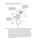
Adjust the laser marker according to the following steps from to .
Adjust the product accuracy first because the accuracy of the laser marker is adjusted aligning the cut surface
of the workpiece.
Make a right-angle ink line on the workpieces of 38 mm in
height and 89 mm in width. Adjust the laser marker and
perform cutting. If the ink line matches the cutting position,
the accuracy adjustment is completed. (Visually check that
the laser marker accuracy is 0.5/100 or less for both the
squareness with the base surface and the squareness with
the fence surface.)
To check the accuracy of the laser marker, move the laser
marker horizontally using the Special Bolt M5
[8]
again and
check that the laser beam is applied to the entire cutting
surface. If the laser beam is applied to the cutting surface in
parallel, the fine fuzz reflects the laser beam and the entire
cutting surface becomes bright.
Turn the Hex. Socket Set Screw M5 x 6
[6]
and the minus
groove at the rear of Laser Holder (A)
[2]
so that laser beam
is applied to the entire cutting surface of the workpiece.
If the laser line gets out of the cutting surface during the laser
line adjustment, turn the Special Bolt M5
[8]
to shift the laser
line onto the cutting surface, top edge or rear edge of the
cutting surface then adjust the accuracy of the laser line.
(Repeat this operation 3 or 4 times depending on the
adjusting conditions of the laser marker.) Refer to the above
(2) and (3) for the relation between the Hex. Socket Set
Screw M5 x 6
[6]
and the laser line, and the relation between
the minus groove at the rear of Laser Holder (A)
[2]
and the
laser line.
First, hold a workpiece of 38 mm in height and 89 mm in
width with the vise and perform right-angle cutting.
Light up the laser marker with the workpiece held in the vise.
Turn the Special Bolt M5
[8]
to shift the laser line onto the
cutting surface, top edge or rear edge of the cutting surface.
1
2
Fig. 52
3
4
Fig. 53
Fig. 54
1
Содержание C12FCH
Страница 27: ... 23 Base packing Packing C Packing E Fig 29 Fig 28 Carton box Upper packing Packing B Packing A Fig 30 ...
Страница 39: ... 35 Wiring diagram C 12LCH Fig 38 2 ...
Страница 40: ... 36 C 12LCH Europe AUS NZL China Fig 39 1 Fig 39 2 ...
Страница 41: ... 37 Fig 40 2 Wiring diagram C 12LC USA CAN Fig 40 1 ...
Страница 42: ... 38 C 12LC Europe NZL Fig 41 1 Fig 41 2 ...
Страница 43: ... 39 Fig 42 2 Wiring diagram C 12FCH USA CAN Fig 42 1 ...
Страница 44: ... 40 C 12FCH Europe NZL Asia Fig 43 1 Fig 43 2 ...
Страница 76: ... 10 ITEM NO CODE NO DESCRIPTION REMARKS NO USED 6 05 C 12LC Printed in Japan 050630N ...
Страница 86: ... 10 ITEM NO CODE NO DESCRIPTION REMARKS NO USED 6 05 C 12FCH Printed in Japan 050630N ...
Страница 87: ......


