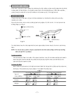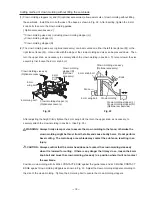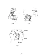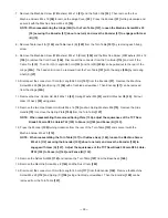
--- 31 ---
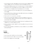
1. Remove the two Tapping Screws (W/Flange) D4 x 25 (Black)
[237]
and the four Tapping Screws (W/Flange)
D4 x 20 (Black)
[246]
, then remove Switch Handle (C)
[247]
. Remove the wire of the Laser Module (A) Ass'y
[12A]
from Cord (B)
[238]
. (Only the Model C 12LCH)
2. Remove the two Machine Screws (W/Washers) M4 x 16
[209]
and the Gear Case Cover Ass'y
[210]
.
3. Remove the Machine Screw (W/Washers) M4 x 12 (Black)
[206]
and the Nylon Clip
[205]
.
4. Remove the Machine Screw (W/Washers) M4 x 10 (Black)
[68]
to remove Indicator (B)
[67]
.
5. Remove the two Machine Screws (W/Washers) M5 x 16
[46]
and remove the Dust Guide Ass'y
[45]
from the
Hinge
[30A]
.
6. Remove the two Hex. Socket Hd. Bolts M6 x 20
[55]
and remove the Laser Holder Ass'y
[80]
from the Hinge
[30A]
.
7. Remove the Split Pin D2 x 12
[7]
using a pair of long-nose pliers. Loosen the Special Bolt M5
[8]
and remove
the Laser Base Ass'y
[10]
and Spring (C)
[5]
.
Fig. 36
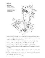
E. Laser marker
Tools required:
• Phillips screwdriver
• Hex. bar wrench 5 mm
• Hex. bar wrench 4 mm
• Hex. bar wrench 2.5 mm
• Long-nose pliers
Содержание C12FCH
Страница 27: ... 23 Base packing Packing C Packing E Fig 29 Fig 28 Carton box Upper packing Packing B Packing A Fig 30 ...
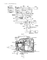
Страница 39: ... 35 Wiring diagram C 12LCH Fig 38 2 ...
Страница 40: ... 36 C 12LCH Europe AUS NZL China Fig 39 1 Fig 39 2 ...
Страница 41: ... 37 Fig 40 2 Wiring diagram C 12LC USA CAN Fig 40 1 ...
Страница 42: ... 38 C 12LC Europe NZL Fig 41 1 Fig 41 2 ...
Страница 43: ... 39 Fig 42 2 Wiring diagram C 12FCH USA CAN Fig 42 1 ...
Страница 44: ... 40 C 12FCH Europe NZL Asia Fig 43 1 Fig 43 2 ...
Страница 76: ... 10 ITEM NO CODE NO DESCRIPTION REMARKS NO USED 6 05 C 12LC Printed in Japan 050630N ...
Страница 86: ... 10 ITEM NO CODE NO DESCRIPTION REMARKS NO USED 6 05 C 12FCH Printed in Japan 050630N ...
Страница 87: ......

